DESCRIPTION
This DTC is output when a malfunction in the L4 detection switch is detected.
|
DTC No. |
Detection Item |
DTC Detection Condition |
Trouble Area |
|---|---|---|---|
|
P2772 |
Four Wheel Drive (4WD) Low Switch Circuit Range / Performance |
|
|
WIRING DIAGRAM
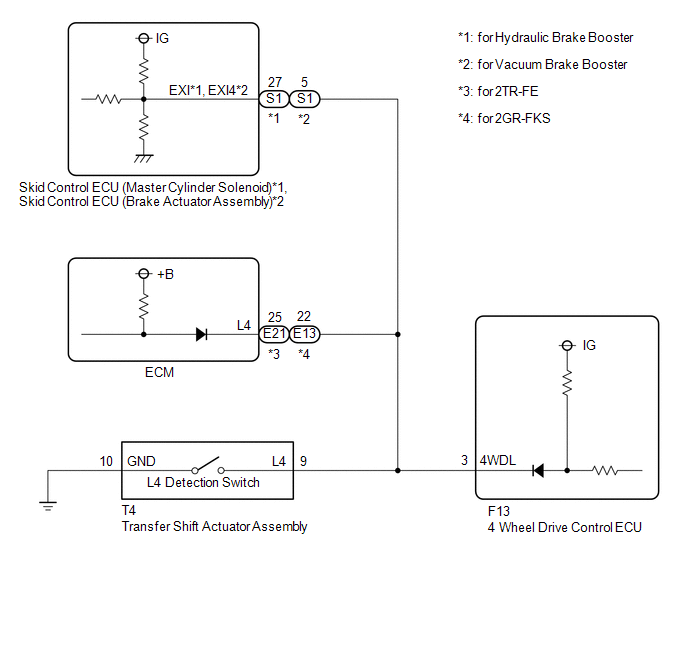
PROCEDURE
|
1. |
CHECK HARNESS AND CONNECTOR (4 WHEEL DRIVE CONTROL ECU - TRANSFER SHIFT ACTUATOR ASSEMBLY) |
(a) Disconnect the F13 4 wheel drive control ECU connector.
(b) Disconnect the T4 transfer shift actuator assembly connector.
(c) for Hydraulic Brake Booster:
Disconnect the S1 skid control ECU (Master Cylinder Solenoid) connector.
for Vacuum Brake Booster:
Disconnect the S1 skid control ECU (brake actuator assembly) connector.
(d) for 2TR-FE:
Disconnect the E21 ECM connector.
for 2GR-FKS:
Disconnect the E13 ECM connector.
(e) Measure the resistance according to the value(s) in the table below.
Standard Resistance:
|
Tester Connection |
Condition |
Specified Condition |
|---|---|---|
|
F13-3 (4WDL) - T4-9 (L4) |
Always |
Below 1 Ω |
|
T4-10 (GND) - Body ground |
Always |
Below 1 Ω |
|
F13-3 (4WDL) or T4-9 (L4) - Body ground |
Always |
10 kΩ or higher |
| NG | .gif) |
REPAIR OR REPLACE HARNESS OR CONNECTOR |
|
.gif)
|
2. |
CHECK TRANSFER SHIFT ACTUATOR ASSEMBLY |
(a) Turn the ignition switch to ON.
(b) Turn the transfer position switch to L4.
(c) Turn the ignition switch off.
(d) Disconnect the T4 transfer shift actuator assembly connector.
|
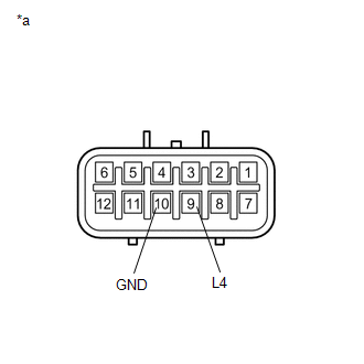
(e) Measure the resistance according to the value(s) in the table below. Standard Resistance:
|
|
| OK | |
REPLACE 4 WHEEL DRIVE CONTROL ECU |
| NG | |
REPLACE TRANSFER SHIFT ACTUATOR ASSEMBLY |