Components
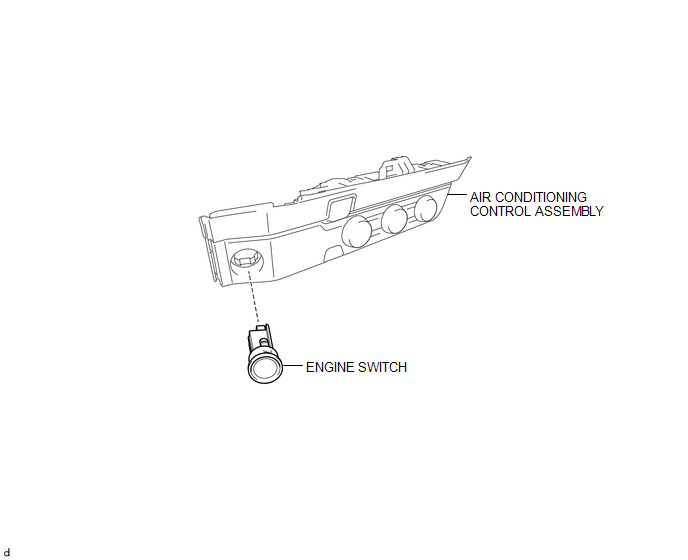
COMPONENTS
ILLUSTRATION
Inspection
INSPECTION
PROCEDURE
1. INSPECT ENGINE SWITCH
(a) Measure the resistance according to the value(s) in the table below.
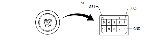 Text in Illustration
|
*a |
Component without harness connected (Engine Switch) |
- |
- |
Standard Resistance:
|
Tester Connection |
Switch Condition |
Specified Condition |
|---|---|---|
|
5 (SS1) - 6 (GND) |
Not pushed |
10 kΩ or higher |
|
1 (SS2) - 6 (GND) |
||
|
5 (SS1) - 6 (GND) |
Pushed |
Below 1 Ω |
|
1 (SS2) - 6 (GND) |
If the result is not as specified, replace the engine switch.
(b) Apply battery voltage between the terminals of the switch, and check the illumination condition of the engine switch.
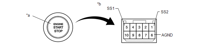 Text in Illustration
|
*a |
Indicator Light |
*b |
Component without harness connected (Engine Switch) |
OK:
|
Measurement Condition |
Specified Condition |
|---|---|
|
Battery positive (+) → Terminal 9 (SWIL) Battery negative (-) → Terminal 6 (GND) |
Illuminates |
HINT:
- If a positive (+) battery lead and a negative (-) battery lead are incorrectly connected, the engine switch indicator light will not illuminate.
- If the voltage is too low, the indicator light will not illuminate.
If the result is not as specified, replace the engine switch.
Installation
INSTALLATION
PROCEDURE
1. INSTALL ENGINE SWITCH
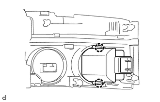
(a) Engage the 2 claws and install the engine switch to the air conditioning control assembly.
2. REMOVE AIR CONDITIONING CONTROL ASSEMBLY
(See page .gif) )
)
Removal
REMOVAL
PROCEDURE
1. REMOVE AIR CONDITIONING CONTROL ASSEMBLY
Seepage .gif)
2. REMOVE ENGINE SWITCH
|
(a) Disengage the 2 claws and remove the engine switch from the air conditioning control assembly. |
|