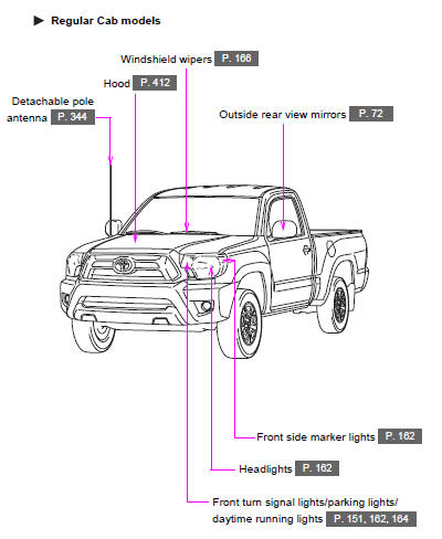
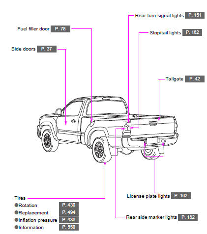
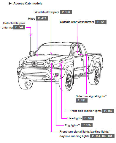
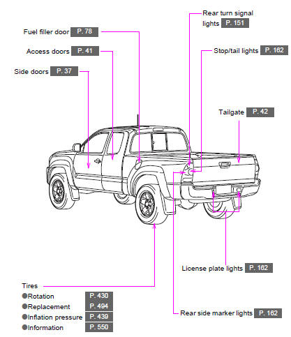
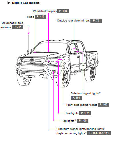
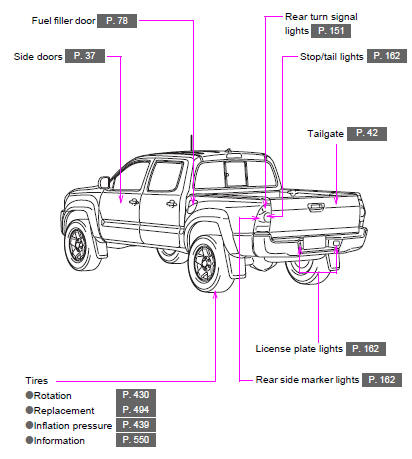
Toyota Tacoma (2005–2015) Owners Manual: Exterior

 Interior
*1: If equipped
* 2: Access Cab and Double Cab models
*3: Vehicles with auto anti- glare inside rear view mirror
*1: If equipped
*2: Vehicles with an automatic transmission
* : If equ ...
Other materials:
Unusual Bank Angle Detected (C1440)
DESCRIPTION
If the skid control ECU (brake actuator assembly) determines that the vehicle
is being driven at a steep bank angle, the skid control ECU (brake actuator assembly)
stores DTC C1440 while VSC operation is temporarily disabled.
This is not a malfunction if the system and sensor circu ...
Clutch Switch Circuit
DESCRIPTION
Clutch switch circuit inspection is necessary for manual transmission vehicles.
When the clutch pedal is released, the ECM receives the positive (+) battery
voltage through the ECU-IG NO. 2 fuse and ignition switch. While the clutch pedal
is depressed, the clutch switch assembly se ...
Precaution
PRECAUTION
PRECAUTION FOR DISCONNECTING CABLE FROM NEGATIVE BATTERY TERMINAL
NOTICE:
When disconnecting the cable from the negative (-) battery terminal,
initialize the following systems after the cable is reconnected.
Click here
If the battery has been discharged and char ...
