Toyota Tacoma (2015-2018) Service Manual: Installation
INSTALLATION
PROCEDURE
1. INSTALL TRANSMISSION WIRE
(a) Coat 2 new O-rings with ATF, and install them to the 2 temperature sensors.
(b) Coat a new O-ring with ATF, and install it to the transmission wire.
(c) Install the transmission wire to the automatic transmission case sub-assembly with the bolt.
Torque:
5.4 N·m {55 kgf·cm, 48 in·lbf}
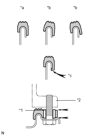
(d) Connect the transmission wire connector.
HINT:
Push up the lever until the claw of the transmission wire connector makes a connection sound.
2. INSTALL TRANSMISSION INSULATOR RH (for 2GR-FKS)
(a) Install the transmission insulator RH to the automatic transmission assembly with the 2 bolts.
Torque:
14 N·m {143 kgf·cm, 10 ft·lbf}
(b) Install the wire harness clamp bracket to the transmission insulator RH with the bolt.
Torque:
13 N·m {127 kgf·cm, 9 ft·lbf}
3. INSTALL TRANSMISSION INSULATOR RH (for 2TR-FE)
(a) Install the transmission insulator RH to the automatic transmission assembly with the 3 bolts.
Torque:
14 N·m {143 kgf·cm, 10 ft·lbf}
4. CONNECT TRANSMISSION WIRE
|
(a) Connect the 7 solenoid valve connectors. Text in Illustration
|
|
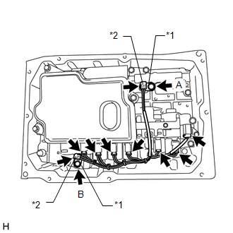
(b) Install the 2 temperature sensors and 2 temperature sensor clamps to the transmission valve body assembly with the bolt.
Torque:
for Bolt A :
10 N·m {102 kgf·cm, 7 ft·lbf}
for Bolt B :
11 N·m {112 kgf·cm, 8 ft·lbf}
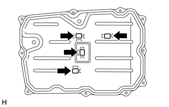
5. INSTALL AUTOMATIC TRANSMISSION OIL PAN SUB-ASSEMBLY
|
(a) Install the 4 transmission oil cleaner magnets to the automatic transmission oil pan sub-assembly as shown in the illustration. |
|
(b) Install a new automatic transmission oil pan gasket to the automatic transmission oil pan sub-assembly.
|
(c) Install the automatic transmission oil pan sub-assembly with automatic transmission oil pan gasket to the automatic transmission case sub-assembly with the 10 bolts. Text in Illustration
Torque: 7.4 N·m {75 kgf·cm, 65 in·lbf} NOTICE:
|
|
6. ADD AUTOMATIC TRANSMISSION FLUID
(See page .gif) )
)
 Removal
REMOVAL
PROCEDURE
1. DRAIN AUTOMATIC TRANSMISSION FLUID
(a) Remove the drain plug and gasket from the automatic transmission
assembly and drain the ATF.
...

Other materials:
Transfer Case Front Oil Seal
Components
COMPONENTS
ILLUSTRATION
Replacement
REPLACEMENT
PROCEDURE
1. DRAIN TRANSFER OIL
2. SUPPORT TRANSMISSION ASSEMBLY
3. REMOVE NO. 3 FRAME CROSSMEMBER SUB-ASSEMBLY
4. REMOVE TRANSFER CASE LOWER PROTECTOR
5. REMOVE FRONT PROPELLER SHAFT ASSEMBLY
(See page )
6. ...
Installation
INSTALLATION
PROCEDURE
1. INSTALL TRANSFER POSITION SWITCH (for 4WD)
Click here
2. INSTALL ENGINE SWITCH
Click here
3. INSTALL AIR CONDITIONING CONTROL ASSEMBLY
(a) Connect the connectors.
(b) Engage the 8 clips to install the air conditioning control assembly.
4. INSTALL RADIO AND DISP ...
Removal
REMOVAL
CAUTION / NOTICE / HINT
HINT:
Use the same procedure for the RH and LH sides.
The procedure listed below is for the LH side.
PROCEDURE
1. REMOVE FRONT DOOR LOWER FRAME BRACKET GARNISH
(See page
)
2. REMOVE FRONT DOOR INSIDE HANDLE BEZEL PLUG
(See page
)
3. ...
