Toyota Tacoma (2015-2018) Service Manual: Engine Immobiliser System Malfunction (B2799,B279986)
DESCRIPTION
This DTC is stored when one of the following occurs: 1) the ECM detects errors in its own communication with the transponder key ECU assembly; 2) the ECM detects errors in the communication lines; or 3) the ECU communication ID between the transponder key ECU assembly and ECM is different and an engine start is attempted.
|
DTC No. |
DTC Detection Condition |
Trouble Area |
DTC Output Confirmation Operation |
|---|---|---|---|
|
B2799*1 |
One of the following conditions is met:
|
|
|
|
B279986*2 |
One of the following conditions is met:
|
|
|
- *1: for 2TR-FE
- *2: for 2GR-FKS
|
Vehicle Condition when Malfunction Detected |
Fail-safe Operation when Malfunction Detected |
|---|---|
|
Engine cannot be started |
- |
|
DTC No. |
Data List and Active Test |
|---|---|
|
B2799*1 |
- |
|
B279986*2 |
- |
- *1: for 2TR-FE
- *2: for 2GR-FKS
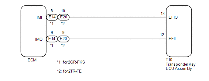
WIRING DIAGRAM
CAUTION / NOTICE / HINT
NOTICE:
- If the transponder key ECU assembly or ECM is replaced, refer to Registration
(See page
.gif) ).
). - After repair, confirm that no DTCs are output by performing "DTC Output Confirmation Operation".
HINT:
If the transponder key ECU assembly DTC is output simultaneously, troubleshoot the transponder key ECU assembly DTCs first.
PROCEDURE
|
1. |
CLEAR DTC |
(a) Clear the DTCs (See page ).
|
.gif)
|
2. |
CHECK FOR DTC |
(a) Perform "DTC Output Confirmation Operation" procedure.
(b) Check for DTCs (See page ).
OK:
DTC B2799*1 or B279986*2 is not output.
- *1: for 2TR-FE
- *2: for 2GR-FKS
|
Result |
Proceed to |
|---|---|
|
DTC B2799 is output*1 |
A |
|
DTC B279986 is output*2 |
B |
|
Other DTCs are output |
C |
|
DTC B2799*1 or B279986*2 is not output |
D |
- *1: for 2TR-FE
- *2: for 2GR-FKS
| B | .gif) |
GO TO STEP 11 |
| C | |
GO TO DIAGNOSTIC TROUBLE CODE CHART |
| D | |
USE SIMULATION METHOD TO CHECK |
|
|
3. |
INSPECT ECM (TERMINAL IMO) |
(a) Using an oscilloscope, check the waveform.
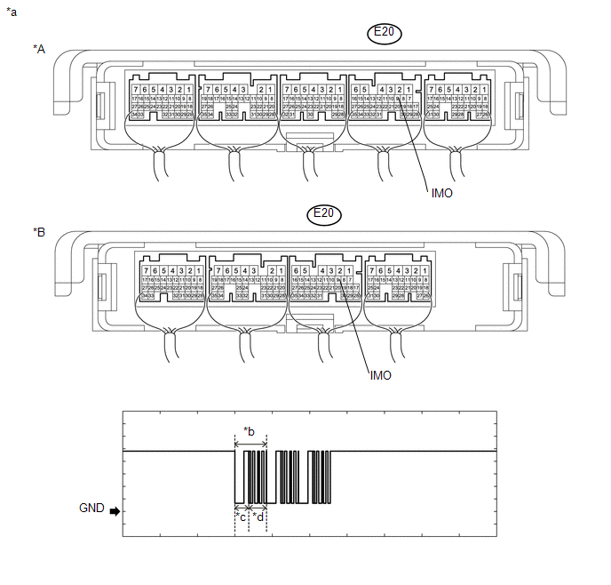 Text in Illustration
|
*A |
for Automatic Transmission |
*B |
for Manual Transmission |
|
*a |
Component with harness connected (ECM) |
*b |
Waveform |
|
*c |
Approximately 160 ms |
*d |
Approximately 270 ms |
Measurement Condition:
|
Tester Connection |
Condition |
Tool Setting |
Specified Condition |
|---|---|---|---|
|
E20-9 (IMO) - Body ground |
Within 3 seconds of starter operation and initial combustion, or within 3 seconds of ignition switch first being turned to ON after cable disconnected and reconnected to negative (-) battery terminal |
2 V/DIV., 500 ms./DIV. |
Pulse generation (See waveform) |
OK:
Waveform is similar to that shown in the illustration.
Result|
Result |
Proceed to |
|---|---|
|
Normal waveform |
A |
|
Terminal IMO stuck low (2.4 V or less) |
B |
|
Terminal IMO stuck high (12 V) or abnormal waveform |
C |
| B | |
GO TO STEP 7 |
| C | |
GO TO STEP 19 |
|
|
4. |
INSPECT ECM (TERMINAL IMI) |
(a) Using an oscilloscope, check the waveform.
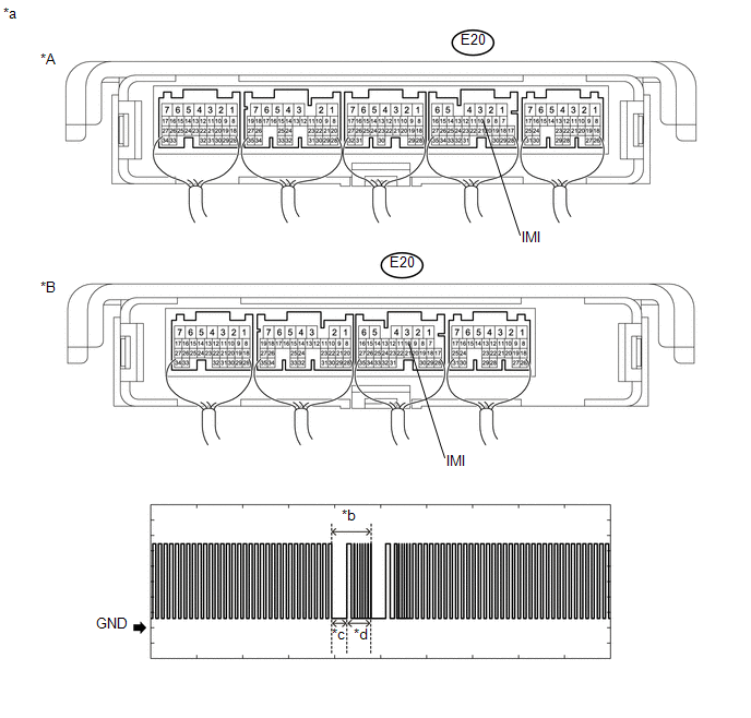 Text in Illustration
|
*A |
for Automatic Transmission |
*B |
for Manual Transmission |
|
*a |
Component with harness connected (ECM) |
*b |
Waveform |
|
*c |
Approximately 160 ms |
*d |
Approximately 270 ms |
Measurement Condition:
|
Tester Connection |
Condition |
Tool Setting |
Specified Condition |
|---|---|---|---|
|
E20-10 (IMI) - Body ground |
Within 3 seconds of starter operation and initial combustion, or within 3 seconds of ignition switch first being turned to ON after cable disconnected and reconnected to negative (-) battery terminal |
2 V/DIV., 500 ms./DIV. |
Pulse generation (See waveform) |
OK:
Waveform is similar to that shown in the illustration.
| NG | |
GO TO STEP 9 |
|
|
5. |
REGISTER ECU COMMUNICATION ID |
(a) Register the ECU communication ID (See page
).
|
|
6. |
CHECK WHETHER ENGINE STARTS |
(a) Using a registered door control transmitter assembly, turn the ignition switch to ON.
(b) Check that the engine starts 5 seconds after the ignition switch was turned to ON.
OK:
Engine starts normally.
| OK | |
END (COMMUNICATION ID REGISTRATION WAS DEFECTIVE) |
| NG | |
GO TO STEP 19 |
|
7. |
INSPECT ECM (IMO TERMINAL VOLTAGE) |
|
(a) Disconnect the ECM connector. |
|
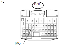
(b) Turn the ignition switch to ON.
(c) Measure the voltage according to the value(s) in the table below.
Standard Voltage:
|
Tester Connection |
Condition |
Specified Condition |
|---|---|---|
|
E20-9 (IMO) - Body ground |
Ignition switch turned to ON using registered door control transmitter assembly |
Terminal IMO stuck low (2.4 V or less) |
|
*a |
Front view of wire harness connector (to ECM) |
|
Result |
Proceed to |
|---|---|
|
Terminal IMO stuck low (2.4 V or less) |
A |
|
Terminal IMO stuck high (12 V) or abnormal waveform |
B |
| B | |
GO TO STEP 19 |
|
|
8. |
CHECK HARNESS AND CONNECTOR (TRANSPONDER KEY ECUASSEMBLY - ECM) |
(a) Disconnect the T10 transponder key ECU assembly connector.
(b) Disconnect the E20 ECM connector.
(c) Measure the resistance according to the value(s) in the table below.
Standard Resistance:
|
Tester Connection |
Condition |
Specified Condition |
|---|---|---|
|
T10-12 (EFII) - E20-9 (IMO) |
Always |
Below 1 Ω |
|
T10-12 (EFII) or E20-9 (IMO) - Body ground |
Always |
10 kΩ or higher |
| NG | |
REPAIR OR REPLACE HARNESS OR CONNECTOR |
|
|
9. |
REPLACE TRANSPONDER KEY ECU ASSEMBLY |
(a) Replace the transponder key ECU assembly with a new one (See page
).
|
|
10. |
CHECK WHETHER ENGINE STARTS |
(a) Using a registered door control transmitter assembly, turn the ignition switch to ON.
(b) Check that the engine starts 5 seconds after the ignition switch was turned to ON.
OK:
Engine starts normally.
| OK | |
END (TRANSPONDER KEY ECU ASSEMBLY WAS DEFECTIVE) |
| NG | |
REPLACE ECM |
|
11. |
INSPECT ECM (TERMINAL IMO) |
(a) Using an oscilloscope, check the waveform.
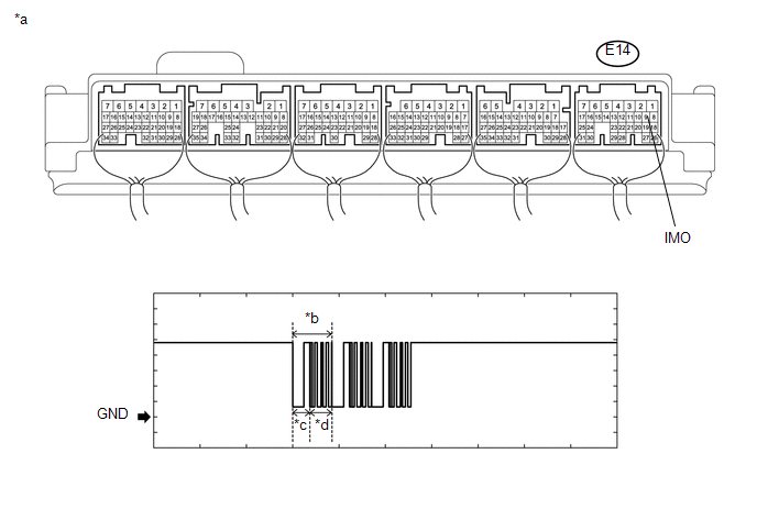 Text in Illustration
|
*a |
Component with harness connected (ECM) |
*b |
Waveform |
|
*c |
Approximately 160 ms |
*d |
Approximately 270 ms |
Measurement Condition:
|
Tester Connection |
Condition |
Tool Setting |
Specified Condition |
|---|---|---|---|
|
E14-9 (IMO) - Body ground |
Within 3 seconds of starter operation and initial combustion, or within 3 seconds of ignition switch first being turned to ON after cable disconnected and reconnected to negative (-) battery terminal |
2 V/DIV., 500 ms./DIV. |
Pulse generation (See waveform) |
OK:
Waveform is similar to that shown in the illustration.
Result|
Result |
Proceed to |
|---|---|
|
Normal waveform |
A |
|
Terminal IMO stuck low (2.4 V or less) |
B |
|
Terminal IMO stuck high (12 V) or abnormal waveform |
C |
| B | |
GO TO STEP 15 |
| C | |
GO TO STEP 19 |
|
|
12. |
INSPECT ECM (TERMINAL IMI) |
(a) Using an oscilloscope, check the waveform.
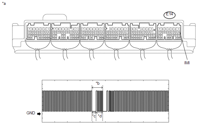 Text in Illustration
|
*a |
Component with harness connected (ECM) |
*b |
Waveform |
|
*c |
Approximately 160 ms |
*d |
Approximately 270 ms |
Measurement Condition:
|
Tester Connection |
Condition |
Tool Setting |
Specified Condition |
|---|---|---|---|
|
E14-8 (IMI) - Body ground |
Within 3 seconds of starter operation and initial combustion, or within 3 seconds of ignition switch first being turned to ON after cable disconnected and reconnected to negative (-) battery terminal |
2 V/DIV., 500 ms./DIV. |
Pulse generation (See waveform) |
OK:
Waveform is similar to that shown in the illustration.
| NG | |
GO TO STEP 17 |
|
|
13. |
REGISTER ECU COMMUNICATION ID |
(a) Register the ECU communication ID (See page
).
|
|
14. |
CHECK WHETHER ENGINE STARTS |
(a) Using a registered door control transmitter assembly, turn the ignition switch to ON.
(b) Check that the engine starts 5 seconds after the ignition switch was turned to ON.
OK:
Engine starts normally.
| OK | |
END (COMMUNICATION ID REGISTRATION WAS DEFECTIVE) |
| NG | |
GO TO STEP 19 |
|
15. |
INSPECT ECM (IMO TERMINAL VOLTAGE) |
|
(a) Disconnect the ECM connector. |
|
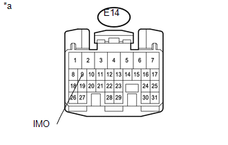
(b) Turn the ignition switch to ON.
(c) Measure the voltage according to the value(s) in the table below.
Standard Voltage:
|
Tester Connection |
Condition |
Specified Condition |
|---|---|---|
|
E14-9 (IMO) - Body ground |
Ignition switch turned to ON using registered door control transmitter assembly |
Terminal IMO stuck low (2.4 V or less) |
|
*a |
Front view of wire harness connector (to ECM) |
|
Result |
Proceed to |
|---|---|
|
Terminal IMO stuck low (2.4 V or less) |
A |
|
Terminal IMO stuck high (12 V) or abnormal waveform |
B |
| B | |
GO TO STEP 19 |
|
|
16. |
CHECK HARNESS AND CONNECTOR (TRANSPONDER KEY ECUASSEMBLY - ECM) |
(a) Disconnect the T10 transponder key ECU assembly connector.
(b) Disconnect the E14 ECM connector.
(c) Measure the resistance according to the value(s) in the table below.
Standard Resistance:
|
Tester Connection |
Condition |
Specified Condition |
|---|---|---|
|
T10-12 (EFII) - E14-9 (IMO) |
Always |
Below 1 Ω |
|
T10-12 (EFII) or E14-9 (IMO) - Body ground |
Always |
10 kΩ or higher |
| NG | |
REPAIR OR REPLACE HARNESS OR CONNECTOR |
|
|
17. |
REPLACE TRANSPONDER KEY ECU ASSEMBLY |
(a) Replace the transponder key ECU assembly with a new one (See page
).
|
|
18. |
CHECK WHETHER ENGINE STARTS |
(a) Using a registered door control transmitter assembly, turn the ignition switch to ON.
(b) Check that the engine starts 5 seconds after the ignition switch was turned to ON.
OK:
Engine starts normally.
| OK | |
END (TRANSPONDER KEY ECU ASSEMBLY WAS DEFECTIVE) |
| NG | |
REPLACE ECM |
|
19. |
REPLACE ECM |
(a) Temporarily replace the ECM with a new one (See page
).
|
|
20. |
REGISTER ECU COMMUNICATION ID |
(a) Register the ECU communication ID (See page
).
|
|
21. |
CHECK WHETHER ENGINE STARTS |
(a) Using a registered door control transmitter assembly, turn the ignition switch to ON.
(b) Check that the engine starts 5 seconds after the ignition switch was turned to ON.
OK:
Engine starts normally.
| OK | |
END (ECM WAS DEFECTIVE) |
| NG | |
REPLACE TRANSPONDER KEY ECU ASSEMBLY |
 Theft Deterrent System Presence Detection (B279C,B279C95)
DESCRIPTION
If an ECM that is incompatible with the engine immobiliser system is installed,
the ECM stores this DTC.
DTC No.
DTC Detection Condition
Trouble Area
...
 Push Switch / Key Unlock Warning Switch Malfunction (B2780)
DESCRIPTION
This DTC is stored if the transponder key ECU assembly does not detect that the
unlock warning switch assembly is ON even when the key is in the ignition key cylinder.
Under normal co ...
Other materials:
Parking Brake Cable
Components
COMPONENTS
ILLUSTRATION
Removal
REMOVAL
PROCEDURE
1. DISCONNECT NO. 2 PARKING BRAKE SHOE ASSEMBLY WITH PARKING BRAKE SHOE LEVER
(See page )
2. REMOVE VOLTAGE INVERTER ASSEMBLY
(See page )
3. REMOVE NO. 2 PARKING BRAKE CABLE ASSEMBLY
(a) Loosen the adjusting n ...
Pressure Control Solenoid "C" Electrical (Shift Solenoid Valve SL3) (P0798)
DESCRIPTION
Changing from 1st to 6th is performed by the ECM turning shift solenoid valves
SL1, SL2, SL3 and SL4 on and off. If an open or short circuit occurs in any of the
shift solenoid valves, the ECM controls the remaining normal shift solenoid valves
to allow the vehicle to be operated ...
System Description
SYSTEM DESCRIPTION
1. ENGINE IMMOBILISER SYSTEM DESCRIPTION
The engine immobiliser system is designed to prevent the vehicle from being stolen.
This system uses the transponder key ECU assembly that stores the key ID codes of
authorized ignition keys. If an attempt is made to start the engine ...
