Toyota Tacoma (2015-2018) Service Manual: Manual Shifting Test
MANUAL SHIFTING TEST
1. PERFORM MANUAL SHIFTING TEST
HINT:
- Using this test, it can be determined whether a problem is in an electrical circuit or if it is a mechanical problem in the transmission.
- If any abnormalities are found in the following test, the problem is in the transmission itself.
(a) Disconnect the connector of the transmission wire.
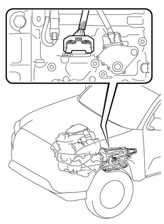
HINT:
It is possible to deactivate the electrical shift control by disconnecting the transmission wire. The gears can then be changed mechanically with the shift lever.
(b) Drive the vehicle with the transmission wire disconnected. Move the shift lever to each position to check whether the gear changes as shown in the table below.
|
Shift Lever Position |
Gear |
|---|---|
|
P |
P |
|
R |
R |
|
D |
3rd |
(c) Connect the connector of the transmission wire.
(d) Clear the DTCs (See page .gif) ).
).
 Initialization
INITIALIZATION
1. RESET MEMORY
NOTICE:
Perform Reset Memory (AT initialization) when replacing the automatic
transmission assembly, transmission valve body assembly or any of the shift ...
 Monitor Drive Pattern
MONITOR DRIVE PATTERN
1. TEST MONITOR DRIVE PATTERN FOR ECT
CAUTION:
Perform this drive pattern on a level surface and strictly observe the posted
speed limits and traffic laws while driving.
HI ...
Other materials:
Dtc Check / Clear
DTC CHECK / CLEAR
NOTICE:
When the diagnosis system is changed from normal mode to check mode or vice versa,
all DTCs and freeze frame data recorded in normal mode are cleared. Before changing
modes, always check and make a note of DTCs and freeze frame data.
HINT:
DTCs which are sto ...
On-vehicle Inspection
ON-VEHICLE INSPECTION
PROCEDURE
1. CONNECT TECHSTREAM
(a) Warm up the engine.
(b) Turn the ignition switch to off.
(c) Connect the Techstream to the DLC3.
(d) Turn the ignition switch to ON.
(e) Turn the Techstream on.
(f) Enter the following menus: Chassis / ABS/VSC/TRAC / Active Test.
2. ...
Communication Error from ECM to VSC (P1631)
DESCRIPTION
The ECM sends signals such as A/T information signals, dynamic radar cruise control
operation signals, brake operation demand signals, and buzzer operation demand signals
to the skid control ECU (brake actuator assembly) when the dynamic radar cruise
control is operating. Therefor ...
