Toyota Tacoma (2015-2018) Service Manual: Removal
REMOVAL
CAUTION / NOTICE / HINT
HINT:
- Use the same procedure for both the RH and LH sides.
- The procedure described below is for the LH side.
PROCEDURE
1. PRECAUTION
NOTICE:
After turning the ignition switch off, waiting time may be required before disconnecting the cable from the negative (-) battery terminal. Therefore, make sure to read the disconnecting the cable from the negative (-) battery terminal notices before proceeding with work.
Click here .gif)
2. DISCONNECT CABLE FROM NEGATIVE BATTERY TERMINAL
CAUTION:
Wait at least 90 seconds after disconnecting the cable from the negative (-) battery terminal to disable the SRS system.
NOTICE:
When disconnecting the cable, some systems need to be initialized after the cable is reconnected.
Click here
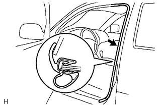
3. REMOVE FRONT DOOR SCUFF PLATE
Click here
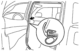
4. REMOVE REAR DOOR SCUFF PLATE
Click here
5. DISCONNECT FRONT DOOR OPENING TRIM WEATHERSTRIP
|
(a) Disconnect the front door opening trim weatherstrip to the extent which allows the removal of the center pillar lower garnish and center pillar upper garnish. |
|
6. DISCONNECT REAR DOOR OPENING TRIM WEATHERSTRIP
|
(a) Disconnect the rear door opening trim weatherstrip to the extent which allows the removal of the center pillar lower garnish and center pillar upper garnish. |
|
7. REMOVE LAP BELT OUTER ANCHOR COVER
Click here
8. DISCONNECT FRONT SEAT OUTER BELT ASSEMBLY
Click here
9. REMOVE CENTER PILLAR LOWER GARNISH
Click here
10. REMOVE CENTER PILLAR UPPER GARNISH
Click here
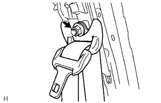
11. REMOVE FRONT SEAT OUTER BELT ASSEMBLY
|
(a) Remove the nut to disconnect the shoulder anchor. |
|
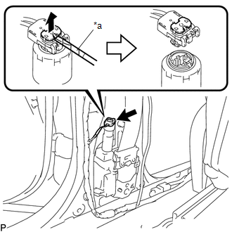
|
(b) Using a screwdriver with its tip wrapped in protective tape, release the locking button to disconnect the connector. Text in Illustration
|
|
|
(c) Remove the bolt. |
|
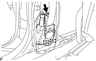
(d) Disengage the 2 guides to remove the front seat outer belt assembly.
12. REMOVE FRONT SHOULDER BELT ANCHOR ADJUSTER ASSEMBLY
|
(a) Remove the 2 bolts. |
|
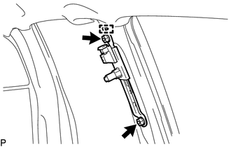
(b) Disengage the guide to remove the front shoulder belt anchor adjuster assembly.
 Installation
INSTALLATION
CAUTION / NOTICE / HINT
HINT:
Use the same procedure for both the RH and LH sides.
The procedure described below is for the LH side.
PROCEDURE
1. INSTALL FRONT SHOU ...
 Disposal
DISPOSAL
CAUTION / NOTICE / HINT
CAUTION:
Before performing pre-disposal deployment of any SRS component, review and closely
follow all applicable environmental and hazardous material regulations ...
Other materials:
ECU Power Source Circuit
DESCRIPTION
The IG circuit is the power source for the tire pressure warning ECU and receiver.
WIRING DIAGRAM
CAUTION / NOTICE / HINT
NOTICE:
When replacing the tire pressure warning ECU and receiver, read the
transmitter IDs stored in the old ECU using the Techstream and write th ...
Meter Illumination does not Dim at Night
DESCRIPTION
In this circuit, the combination meter assembly auto dimmer signals from the
main body ECU using the CAN communication system (CAN V1 Bus). When the combination
meter assembly an auto dimmer signal, it dims the meter illumination (warning and
indicator lights). The main body ECU ( ...
Radio Receiver Power Source Circuit
DESCRIPTION
This is the power source circuit to operate the radio and display receiver assembly.
WIRING DIAGRAM
CAUTION / NOTICE / HINT
NOTICE:
Inspect the fuses for circuits related to this system before performing
the following inspection procedure.
PROCEDURE
...
