Toyota Tacoma (2015-2018) Service Manual: Removal
REMOVAL
CAUTION / NOTICE / HINT
HINT:
- Use the same procedures for both the LH and RH sides.
- The procedure described below is for the LH side.
PROCEDURE
1. REMOVE FRONT DOOR LOWER FRAME BRACKET GARNISH
.gif)
2. REMOVE FRONT DOOR INSIDE HANDLE BEZEL PLUG
3. REMOVE FRONT ARMREST BASE UPPER PANEL SUB-ASSEMBLY
4. REMOVE FRONT DOOR TRIM BOARD SUB-ASSEMBLY
5. REMOVE OUTER REAR VIEW MIRROR ASSEMBLY
|
(a) Disconnect the connector. |
|
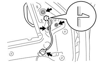
(b) Remove the 3 nuts.
(c) Disengage the claw to remove the outer rear view mirror assembly.
 Components
COMPONENTS
ILLUSTRATION
ILLUSTRATION
...
 Disassembly
DISASSEMBLY
CAUTION / NOTICE / HINT
HINT:
Use the same procedures for both the LH and RH sides.
The procedure described below is for the LH side.
PROCEDURE
1. REMOVE OUTER MIRRO ...
Other materials:
4wd Control Ecu
Components
COMPONENTS
ILLUSTRATION
Installation
INSTALLATION
PROCEDURE
1. INSTALL 4 WHEEL DRIVE CONTROL ECU
(a) Engage the 2 guides to install the 4 wheel drive control ECU.
(b) Install the 2 bolts.
Torque:
5.0 N·m {51 kgf·cm, 44 in·lbf}
(c) Connect the 2 connectors.
2. INSTALL ...
System Voltage Circuit Short to Ground or Open (P056014)
DESCRIPTION
The battery supplies power to the ECM even when the ignition switch is off. This
power allows the ECM to store data such as DTC history, freeze frame data and fuel
trim values. If the battery voltage falls below a minimum level, the ECM data is
cleared and the ECM determines that ...
Installation
INSTALLATION
CAUTION / NOTICE / HINT
CAUTION:
Some of these service operations affect the SRS airbag system. Read
the precautionary notices concerning the SRS airbag system before servicing
(See page ).
If the side airbag was deployed, replace the front seat assembly with
...
