Toyota Tacoma (2015-2018) Service Manual: Components
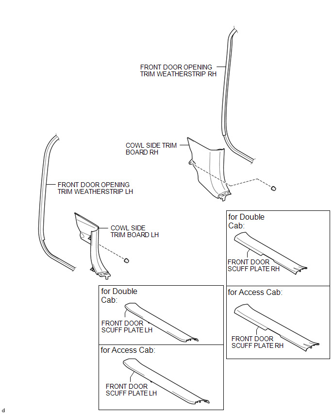
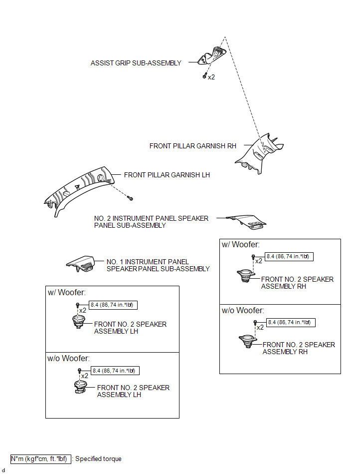
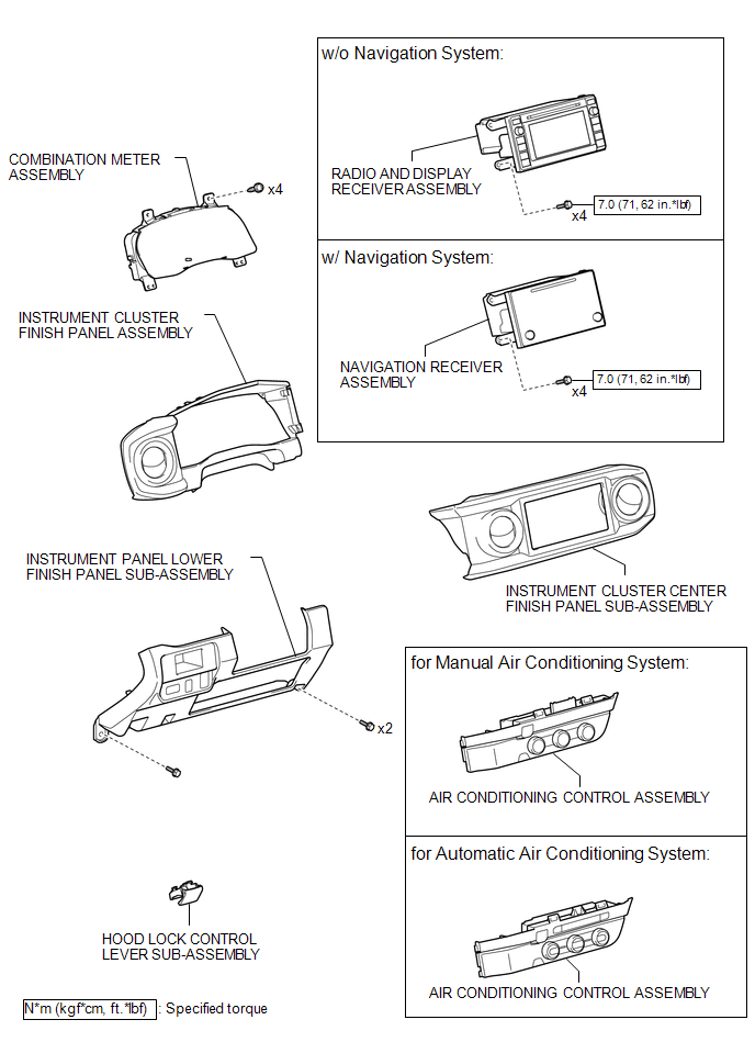
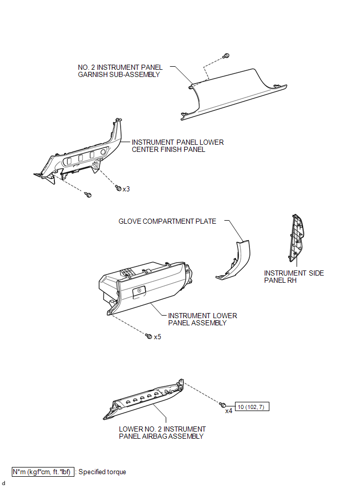
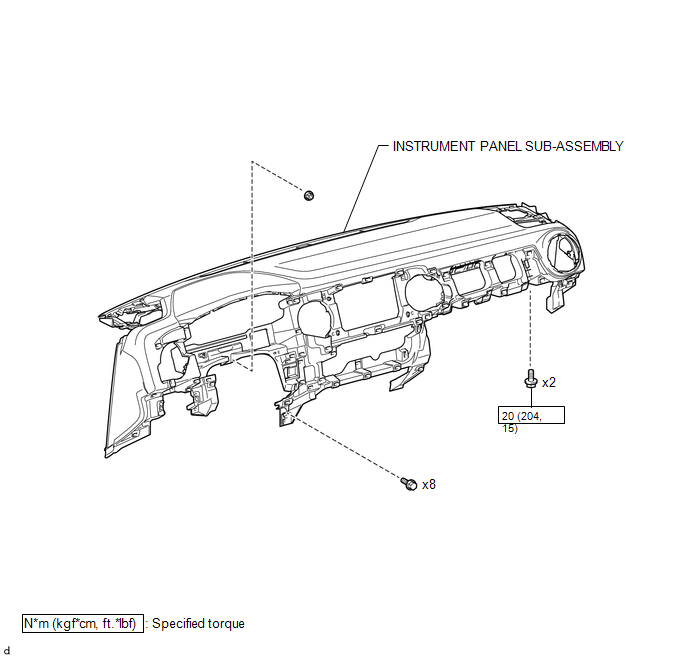
COMPONENTS
ILLUSTRATION
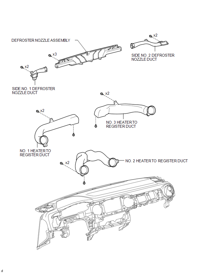
ILLUSTRATION
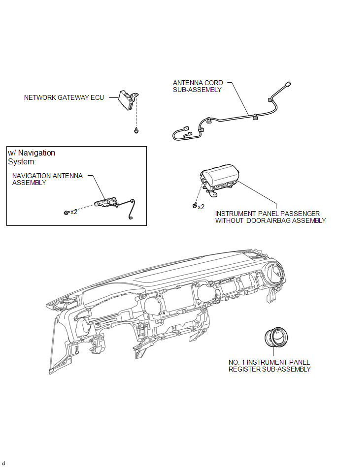
ILLUSTRATION
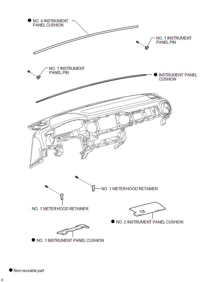
ILLUSTRATION
ILLUSTRATION
ILLUSTRATION
ILLUSTRATION
ILLUSTRATION
 Precaution
PRECAUTION
1. PRECAUTION FOR VEHICLE WITH SRS AIRBAG AND SEAT BELT PRETENSIONER
(a) Some operations in this section may affect the SRS airbags. Prior to performing
the corresponding operations, re ...
 Disassembly
DISASSEMBLY
PROCEDURE
1. REMOVE NO. 1 HEATER TO REGISTER DUCT
(a) Remove the 2 screws <F> and screw <D>.
(b) Disengage the 2 g ...
Other materials:
Active head restraints (Access Cab and Double Cab models only)
When the occupantÔÇÖs back presses against the seatback during a rear-end collision,
the head restraint moves slightly forward to help reduce the risk of whiplash on
the seat occupant.
■Active head restraints
Even small forces applied to the seatback may cause the head restraint to mov ...
Clutch Pedal Switch
On-vehicle Inspection
ON-VEHICLE INSPECTION
PROCEDURE
1. CHECK CLUTCH START SYSTEM
(a) Check that the engine does not start when the clutch pedal is released.
(b) Check that the engine starts when the clutch pedal is fully depressed.
If necessary, replace the clutch start switch assembly.
...
Disassembly
DISASSEMBLY
PROCEDURE
1. INSPECT PROPELLER SHAFT UNIVERSAL JOINT SPIDER BEARING
(a) Check the spider bearings for wear and damage.
(b) Check each spider bearings axial play by turning the yoke while holding the
shaft tightly.
Maximum bearing axial play:
0 to 0.05 mm (0 to 0.00197 in.)
If t ...
