Toyota Tacoma (2015-2018) Service Manual: Removal
REMOVAL
CAUTION / NOTICE / HINT
CAUTION:
Some of these service operations affect the SRS airbag system. Read the precautionary
notices concerning the SRS airbag system before servicing (See page
.gif) ).
).
HINT:
- Use the same procedure for both the RH and LH sides.
- The procedure described below is for the LH side.
PROCEDURE
1. PRECAUTION
CAUTION:
Be sure to read Precaution thoroughly before servicing (See page
).
NOTICE:
After turning the ignition switch off, waiting time may be required before disconnecting the cable from the negative (-) battery terminal. Therefore, make sure to read the disconnecting the cable from the negative (-) battery terminal notices before proceeding with work.
Click here
2. DISCONNECT CABLE FROM NEGATIVE BATTERY TERMINAL
CAUTION:
Wait at least 90 seconds after disconnecting the cable from the negative (-) battery terminal to disable the SRS system.
NOTICE:
When disconnecting the cable, some systems need to be initialized after the cable is reconnected.
Click here
3. REMOVE FRONT DOOR SCUFF PLATE
4. REMOVE REAR DOOR SCUFF PLATE
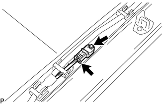
5. REMOVE SIDE AIRBAG SENSOR ASSEMBLY
(a) Disconnect the connector from the side airbag sensor.
NOTICE:
When disconnecting any airbag connector, take care not to damage the airbag wire harness.
(1) Push and hold the white housing lock, and slide the yellow outer connector locking sleeve.
.png)
(2) Push and hold the white housing lock again, and slide the yellow outer connector locking sleeve to disconnect the connector.
(b) Remove the bolt and side airbag sensor.
NOTICE:
Loosen the bolt while holding the door side airbag sensor because the side airbag sensor pin (stopper) is easily damaged.
 Installation
INSTALLATION
CAUTION / NOTICE / HINT
CAUTION:
Some of these service operations affect the SRS airbag system. Read the precautionary
notices concerning the SRS airbag system before servicing (See ...

Other materials:
On-vehicle Inspection
ON-VEHICLE INSPECTION
PROCEDURE
1. INSPECT CAMSHAFT TIMING GEAR BOLT
(a) Remove the camshaft timing oil control solenoid assembly (See page
).
(b) Check that the plunger strokes when the plunger in the center of
the camshaft timing gear bolt is pressed.
Standard stroke:
4 ...
Disassembly
DISASSEMBLY
CAUTION / NOTICE / HINT
HINT:
Use the same procedure for the RH side and LH side.
The following procedure is for the LH side.
When removing the No. 2 front wheel opening extension pad or No. 1 front
wheel opening extension pad or front wheel opening extension pad, ...
Radio Broadcast cannot be Received or Poor Reception
PROCEDURE
1.
CHECK NAVIGATION RECEIVER ASSEMBLY
(a) Check the radio automatic station search function.
(1) Check the radio automatic station search function by activating it.
Result
Result
Proceed to
Automatic station search ...
