Toyota Tacoma (2015-2018) Service Manual: Disassembly
DISASSEMBLY
PROCEDURE
1. REMOVE MILLIMETER WAVE RADAR WIRE (w/ Toyota Safety Sense P)
Click here .gif)
2. REMOVE MILLIMETER WAVE RADAR SENSOR ASSEMBLY (w/ Toyota Safety Sense P)
Click here
3. REMOVE NO. 1 RADIATOR GRILLE GARNISH
(a) When Replacing the No. 1 Radiator Grille Garnish:
(1) Apply protective tape around the spring nut.
.png) |
Protective Tape |
|
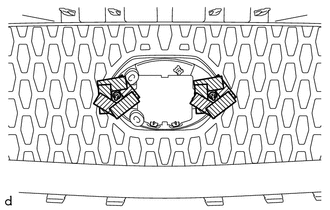
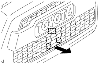
(2) Using a plier nipper (side cutters), cut the No. 1 radiator grille garnish at the positions shown in the illustration. |
|
|
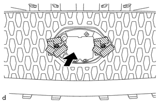
(3) Push the No. 1 radiator grille garnish to remove the 2 spring nuts as shown in the illustration. CAUTION: Make sure to cover the spring nuts with a piece of cloth or equivalent to prevent them from flying off during removal. |
|
|
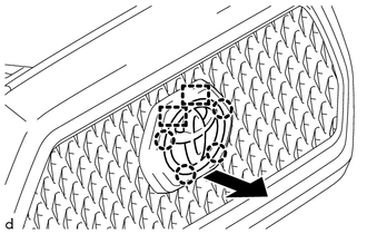
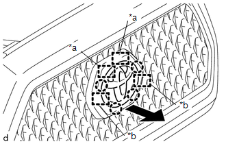
(4) For type A and type B, disengage the 4 claws and 2 pins as shown in the illustration to remove the No. 1 radiator grille garnish. |
|
|
(5) For type C, disengage the 2 claws and the guide as shown in the illustration to remove the No. 1 radiator grille garnish. |
|
(b) When Replacing the Radiator Grille Sub-Assembly:
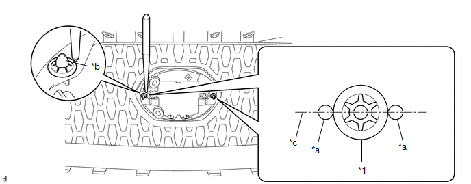
(1) Using a center punch, make a depression at the positions shown in the illustration.
|
*1 |
Spring Nut |
- |
- |
|
*a |
Depression |
*b |
Pin of No. 1 Radiator Grille Garnish |
|
*c |
Center Line |
- |
- |
HINT:
- Make sure to make the depressions so they are aligned with the center line of the pin of the No. 1 radiator grille garnish.
- Make sure to make the depressions correctly so that a plier nipper (side cutters) can be used to pinch the spring nuts.
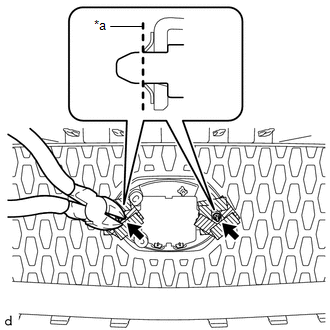
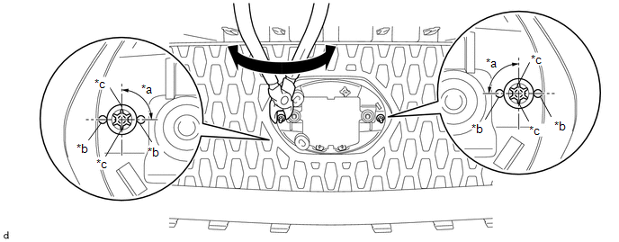
(2) Using a plier nipper (side cutters), rotate the 2 spring nuts to align the cutouts of each spring nut as shown in the illustration.
|
*a |
90° |
*b |
Depression |
|
*c |
Cutout |
- |
- |
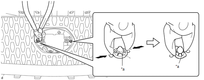
(3) Using a plier nipper (side cutters), deform each spring nut as shown in the illustration and then remove the 2 spring nuts.
|
*a |
Cutout |
- |
- |
|
(4) For type A and type B, disengage the 4 claws and 2 guides and 2 pins as shown in the illustration to remove the No. 1 radiator grille garnish. |
|
|
(5) For type C, disengage the 2 claws and 3 guides as shown in the illustration to remove the No. 1 radiator grille garnish. |
|

4. REMOVE RADIATOR GRILLE MOULDING
|
(a) Remove the 8 screws. |
|
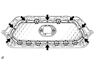
(b) Disengage the 8 claws to remove the radiator grille moulding.
 Removal
REMOVAL
PROCEDURE
1. REMOVE RADIATOR GRILLE
(a) w/ Toyota Safety Sense P
(1) Disconnect the connector.
(2) Disengage the clamp.
(b ...
 Installation
INSTALLATION
PROCEDURE
1. INSTALL RADIATOR GRILLE
(a) Engage the 10 guides to install the radiator grille.
(b) Install the 2 clips.
(c) Install the 2 screws.
(d) Remove the protective tape.
(e) ...
Other materials:
CD cannot be Inserted / Played or CD is Ejected Right After Insertion
PROCEDURE
1.
CHECK IF A PROPER CD IS INSERTED
(a) Make sure that the CD is an audio CD or a CD with an MP3, WMA or AAC file,
and that it is not deformed, flawed, stained, deteriorated or otherwise defective.
OK:
CD is normal.
HINT:
Translucent or uniq ...
Removal
REMOVAL
CAUTION / NOTICE / HINT
NOTICE:
When replacing the forward recognition camera, replace it with a new
one.
Do not touch the camera lens or the front windshield glass in front
of the camera.
If the forward recognition camera has been struck or dropped, replace
it ...
Installation
INSTALLATION
PROCEDURE
1. INSTALL PARK/NEUTRAL POSITION SWITCH
HINT:
Make sure that the manual valve lever shaft has not been rotated prior to installing
the park/neutral position switch as the detent spring may become detached from the
manual valve lever shaft.
(a) Clean the bolt and bolt ...
