Toyota Tacoma (2015-2018) Service Manual: Diagnosis System
DIAGNOSIS SYSTEM
1. DESCRIPTION
The ECU stores trouble codes when malfunctions occur.
The diagnostic system allows for reading of the trouble codes from the DLC3.
Use the Techstream to help diagnose and repair the problem.
2. CHECK DLC3
(a) Check the DLC3 (See page .gif) ).
).
3. INSPECT BATTERY VOLTAGE
(a) Measure the battery voltage.
Standard voltage:
11 to 14 V
If the voltage is below 11 V, recharge or replace the battery.
4. SELF-DIAGNOSTIC MODE
(a) Connect the Techstream to the DLC3.
(b) Turn the engine switch on (IG).
(c) Turn the Techstream on.
(d) Enter the following menus: Body Electrical / Smart Key / Utility / Wireless Door Lock Diagnosis Mode.
(e) Proceed to the next step in accordance with the prompts on the Techstream screen.
HINT:
The electrical key transmitter uses 2 different frequencies alternately for communication. When in self diagnostic mode, one of the channels can be selected or the channels can be automatically switched.
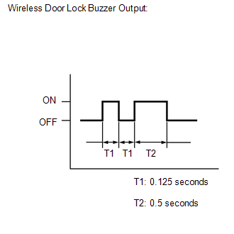
(f) Check that the system has switched to self-diagnostic mode by checking the wireless door lock buzzer output pattern.
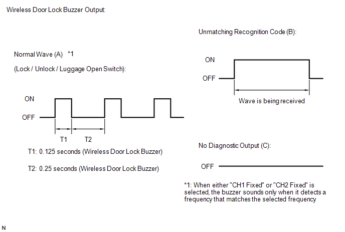
(g) Check the diagnostic outputs when the electrical key transmitter sub-assembly switch is held down.
The diagnostic outputs can be checked by the interior light and wireless door lock buzzer patterns.
 Result
|
Wireless Door Lock Buzzer Output |
Suspected Area |
|---|---|
|
A |
Normal (No malfunction) |
|
B |
Register wireless code |
|
C |
Wave interference or malfunction of a related component |
 Problem Symptoms Table
PROBLEM SYMPTOMS TABLE
HINT:
Use the table below to help determine the cause of problem symptoms.
If multiple suspected areas are listed, the potential causes of the symptoms
are lis ...
 Dtc Check / Clear
DTC CHECK / CLEAR
1. CHECK FOR DTC
HINT:
When using the Techstream with the engine switch off to troubleshoot:
Connect the Techstream to the DLC3 and turn a courtesy light switch on and off
at 1 ...
Other materials:
Engine Switch Illumination Circuit
DESCRIPTION
The illuminated entry system controls the engine switch illumination.
WIRING DIAGRAM
PROCEDURE
1.
READ VALUE USING TECHSTREAM (POWER/ENGINE SW LIGHT)
(a) Connect the Techstream to the DLC3.
(b) Turn the engine switch to ON.
(c) Turn the Techstream ...
Using the radio
Select “AM” or “FM” on the “Select Audio Source” screen to begin listening
to the radio.
Audio control screen
“Select Audio Source” screen
appears
Preset stations
Select to display RBDS text
message
Scanning for receivable station
Sele ...
Open or Short in Rear Speed Sensor RH Circuit (C1407,C1408)
DESCRIPTION
Refer to DTCs C1401 and C1402 (See page ).
DTC Code
DTC Detection Condition
Trouble Area
C1407
C1408
Either condition is met:
An open in the speed sensor signal circuit continues for 0.5
seconds or mor ...
