Toyota Tacoma (2015-2018) Service Manual: Data List / Active Test
DATA LIST / ACTIVE TEST
1. DATA LIST
HINT:
Using the Techstream to read the Data List allows the values or states of switches, sensors, actuators and other items to be read without removing any parts. This non-intrusive inspection can be very useful because intermittent conditions or signals may be discovered before parts or wiring is disturbed. Reading the Data List information early in troubleshooting is one way to save diagnostic time.
NOTICE:
In the table below, the values listed under "Normal Condition" are reference values. Do not depend solely on these reference values when deciding whether a part is faulty or not.
(a) Connect the Techstream to the DLC3.
(b) Turn the ignition switch to ON.
(c) Turn the Techstream on.
(d) Enter the following menus: Body Electrical / Immobiliser / Data List.
(e) Read the Data List according to the display on the Techstream.
Immobiliser|
Tester Display |
Measurement Item/Range |
Normal Condition |
Diagnostic Note |
|---|---|---|---|
|
D Door Courtesy SW |
Driver door courtesy light switch signal / OFF or ON |
OFF: Driver door closed ON: Driver door open |
- |
|
Key SW |
Unlock warning switch signal / OFF or ON |
OFF: No key in ignition key cylinder ON: Key inserted in ignition key cylinder |
- |
|
IG SW*2 |
Ignition switch signal / ON or OFF |
ON: Ignition switch ON OFF: Ignition switch ACC or off |
- |
|
Immobiliser*2 |
Engine immobiliser system status determined by transponder key ECU assembly / Set or Unset |
Set: Engine immobiliser set (engine start prohibited [no key in ignition key cylinder]) Unset: Engine immobiliser unset (engine start permitted [key inserted in ignition key cylinder]) |
When the engine immobiliser system does not change to the unset state, this item can be used to determine if the cause is the transponder key ECU assembly. |
|
Response |
Key response to signal from transponder key ECU assembly / OK or NG |
OK: Key responds to signal from transponder key ECU assembly NG: Key does not respond to signal from transponder key ECU assembly |
Problems may be caused by the following:
|
|
Frame Error |
State of data sent from key / OK or NG |
OK: No problem with data sent from key NG: Problem with data sent from key |
Problems may be caused by the following:
|
|
Different Serial Number*1 |
Vehicle serial number / OK or NG |
OK: Signal from transponder chip and vehicle serial number stored in transponder key ECU assembly match NG: Signal from transponder chip and vehicle serial number stored the transponder key ECU assembly do not match |
Problems may be caused by the following:
|
|
Different Encrypt Code*1 |
Code status between transponder chip and transponder key ECU assembly / OK or NG |
OK: Codes of transponder chip and transponder key ECU assembly match NG: Codes of transponder chip and transponder key ECU assembly do not match |
Problems may be caused by the following:
|
|
Abnormal Status*1 |
Transponder chip status signal / OK or NG |
OK: Transponder chip status signal normal NG: Transponder chip status signal malfunction (malfunction in code computation in key/transponder key ECU assembly) |
Problems may be caused by the following:
|
|
Bcc Malfunction*1 |
Bcc signal status of transponder chip / OK or NG |
OK: Bcc signal normal NG: Bcc signal malfunction (malfunction in code computation in key/transponder key ECU assembly) |
Problems may be caused by the following:
|
|
Sub Key |
Not available / Unreg or Reg |
- |
- |
|
Master Key |
Whether master key ID code matches ID code registered in transponder key ECU assembly / Unreg or Reg |
Unreg: ID code of master key does not match ID code registered in transponder key ECU assembly Reg: ID code of master key matches ID code registered in transponder key ECU assembly |
- |
|
Transponder S-code |
Number of registered sub-keys / min.: 0, max.: 15 |
Number of registered sub-keys |
- |
|
Transponder M-code |
Number of registered master keys / min.: 0, max.: 15 |
Number of registered master keys |
- |
|
Reg Code Space Full |
Key registration code memory space full / No or Yes |
Yes: Cannot register any more key codes No: Possible to register more key codes |
- |
|
+B |
+B judgment / Normal or Break |
Normal: Battery power supply normal Break: Battery power supply malfunctioning |
- |
|
Antenna Coil Status |
Antenna coil condition / Normal or Fail |
Normal: Antenna coil normal Fail: Antenna coil malfunctioning |
- |
|
EEPROM Status |
EEPROM status / OK or NG |
OK: Data OK NG: Data error |
- |
|
E/G Start Permission*2 |
Engine start permission / NG or OK |
NG: Engine start not permitted OK: Engine start permitted |
- |
|
Immobi ECU Comm Spd |
Immobiliser ECU communication speed / Unknown, 50bps, No Res or 200bps |
Unknown: ECU communication speed unknown 50bps: ECU communication speed 50 bps No Res: No response regarding ECU communication speed 200bps: ECU communication speed 200 bps |
- |
|
The Number of DTCs |
Number of DTCs / Min.: 0, Max.: 255 |
Number of stored DTCs |
- |
HINT:
- *1: This indicates that there is a problem with the communication format between the key and transponder key ECU assembly. Electric wave interference, key or transponder key ECU assembly malfunctions, the key of another vehicle being used, etc. are possible causes.
- *2: Refer to the following Data List items of an actual vehicle.
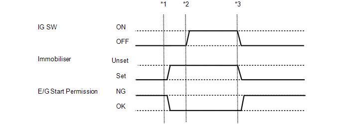
- *1: Without depressing the brake pedal (for Automatic Transmission) or clutch pedal (for Manual Transmission), insert the key into the ignition key cylinder and turn the ignition switch to ACC.
- *2: Without depressing the brake pedal (for Automatic Transmission) or clutch pedal (for Manual Transmission), turn the ignition switch to ON.
- *3: Turn the ignition switch off and remove the key from the ignition key cylinder.
(f) Enter the following menus: Powertrain / Engine or Engine and ECT / Data List.
(g) Read the Data List according to the display on the Techstream.
Engine (for 2GR-FKS)|
Tester Display |
Measurement Item/Range |
Normal Condition |
Diagnostic Note |
|---|---|---|---|
|
Immobiliser Fuel Cut |
Status of immobiliser fuel cut / ON or OFF |
- |
- |
|
Tester Display |
Measurement Item/Range |
Normal Condition |
Diagnostic Note |
|---|---|---|---|
|
Immobiliser Fuel Cut |
Status of immobiliser fuel cut / ON or OFF |
- |
- |
2. ACTIVE TEST
HINT:
Using the Techstream to perform Active Tests allows relays, VSVs, actuators and other items to be operated without removing any parts. This non-intrusive functional inspection can be very useful because intermittent operation may be discovered before parts or wiring is disturbed. Performing Active Tests early in troubleshooting is one way to save diagnostic time. Data List information can be displayed while performing Active Tests.
(a) Connect the Techstream to the DLC3.
(b) Turn the ignition switch to ON.
(c) Turn the Techstream on.
(d) Enter the following menus: Body Electrical / Immobiliser or Main Body / Active Test.
(e) Perform the Active Test according to the display on the Techstream.
Immobiliser|
Tester Display |
Test Part |
Control Range |
Diagnostic Note |
|---|---|---|---|
|
Security Indicator |
Security indicator light |
ON/OFF |
- |
|
Tester Display |
Test Part |
Control Range |
Diagnostic Note |
|---|---|---|---|
|
Security Indicator |
Security indicator light |
OFF/ON |
- |
 Dtc Check / Clear
DTC CHECK / CLEAR
1. CHECK FOR TRANSPONDER KEY ECU ASSEMBLY DTC
(a) Connect the Techstream to the DLC3.
(b) Turn the ignition switch to ON.
(c) Turn the Techstream on.
(d) Enter the following men ...
 Diagnostic Trouble Code Chart
DIAGNOSTIC TROUBLE CODE CHART
HINT:
If a trouble code is stored during the DTC check, inspect the trouble areas listed
for that code. For details of the code, refer to "See page" below.
...
Other materials:
Crawl Indicator Light Remains ON
DESCRIPTION
When CRAWL starts after operating the CRAWL switch (drive monitor switch), the
CRAWL indicator light turns on. While CRAWL is in the process of stopping, the CRAWL
indicator light begins blinking. When CRAWL totally stops, the CRAWL indicator light
turns off.
WIRING DIAGRAM
CA ...
AUTO LSD Indicator Light does not Come ON
DESCRIPTION
The AUTO LSD does not operate even if the VSC OFF switch is pressed under the
following conditions:
The brake system is faulty.
The temperature inside the hydraulic brake booster increases and the
AUTO LSD operation is suspended.
WIRING DIAGRAM
CAUTION / NOTI ...
Outside rear view mirrors
Mirror angle can be adjusted.
Power-adjustable type
Select a mirror to adjust.
(L: left or R: right)
Adjust the mirror up, down, in or
out using the switch.
Manually adjustable type
Adjust the mirror up, down, in or out by pushing the mirror surface.
Folding back the mirrors
...
