Toyota Tacoma (2015-2018) Service Manual: Components
COMPONENTS
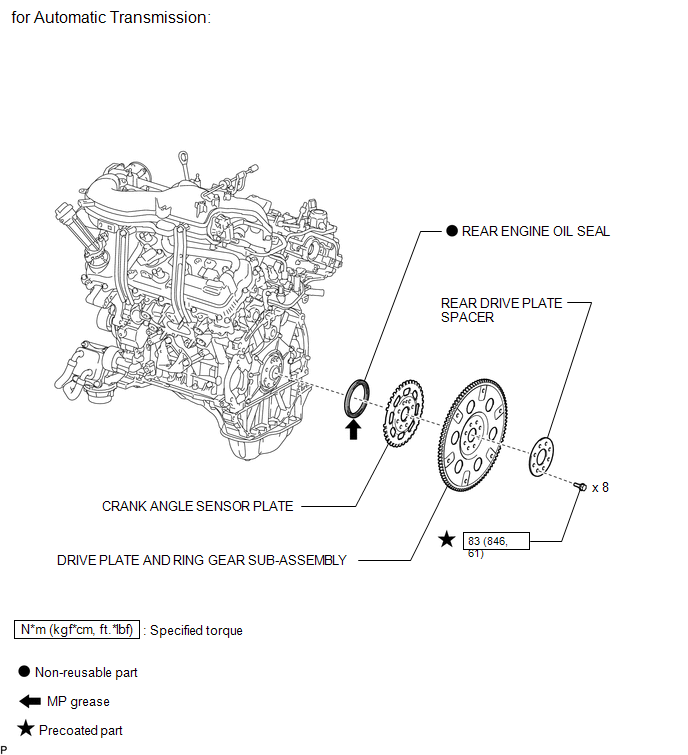
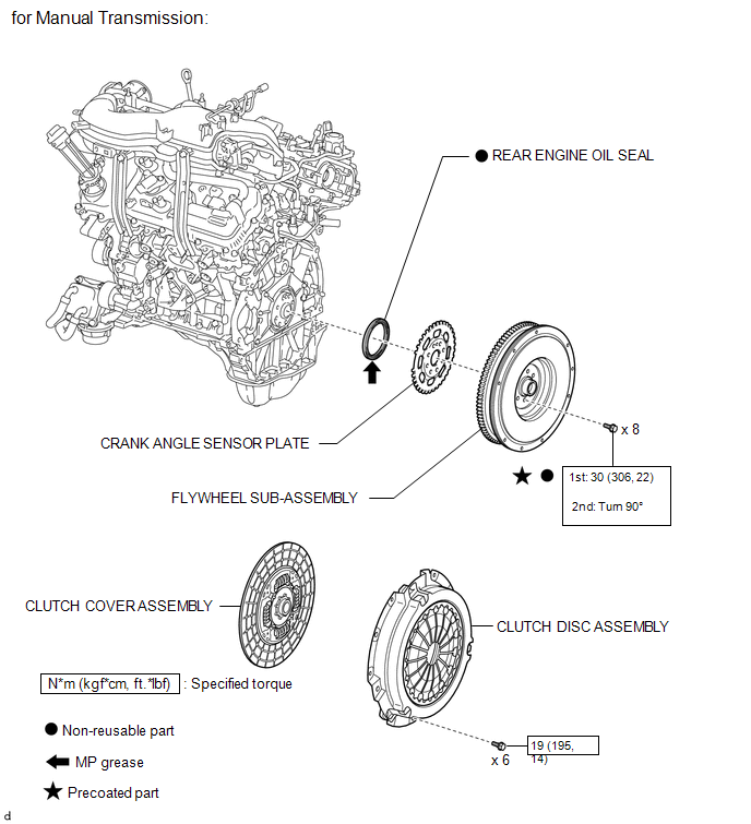
ILLUSTRATION
ILLUSTRATION

 Removal
REMOVAL
PROCEDURE
1. REMOVE AUTOMATIC TRANSMISSION ASSEMBLY (for Automatic Transmission)
Transmission
See page
AC60E
AC60F
...
Other materials:
How To Proceed With Troubleshooting
CAUTION / NOTICE / HINT
HINT:
Use these procedures to troubleshoot the combination meter.
*: Use the Techstream.
PROCEDURE
1.
VEHICLE BROUGHT TO WORKSHOP
NEXT
2.
...
Installation
INSTALLATION
PROCEDURE
1. INSTALL POWER STEERING LINK
(a) Insert the power steering link into the vehicle in the order shown in the
illustration.
Install in this Direction (1)
Install in this Direction (2)
(b) Using SST, inst ...
Radio Broadcast cannot be Received or Poor Reception
PROCEDURE
1.
CHECK RADIO AND DISPLAY RECEIVER ASSEMBLY
(a) Check the radio automatic station search function.
(1) Check the radio automatic station search function by activating it.
Result
Result
Proceed to
Automatic station ...
