Toyota Tacoma (2015-2018) Service Manual: Removal
REMOVAL
PROCEDURE
1. REMOVE AUTOMATIC TRANSMISSION ASSEMBLY (for Automatic Transmission)
|
Transmission |
See page |
|---|---|
|
AC60E |
|
|
AC60F |
|
2. REMOVE MANUAL TRANSMISSION ASSEMBLY (for Manual Transmission)
(See page .gif) )
)
3. REMOVE CLUTCH COVER ASSEMBLY (for Manual Transmission)
4. REMOVE CLUTCH DISC ASSEMBLY (for Manual Transmission)
5. REMOVE DRIVE PLATE AND RING GEAR SUB-ASSEMBLY (for Automatic Transmission)
6. REMOVE FLYWHEEL SUB-ASSEMBLY (for Manual Transmission)
7. REMOVE REAR ENGINE OIL SEAL
|
(a) Using a knife, cut off the lip of the rear engine oil seal. Text in Illustration
|
|
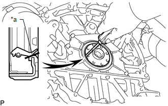
(b) Using a screwdriver, pry out the rear engine oil seal.
NOTICE:
Do not damage the surface of the rear engine oil seal press fit hole or crankshaft.
HINT:
Tape the screwdriver tip before use.
 Components
COMPONENTS
ILLUSTRATION
ILLUSTRATION
...
 Installation
INSTALLATION
PROCEDURE
1. INSTALL REAR ENGINE OIL SEAL
(a) Apply MP grease to the lip of a new rear engine oil seal.
NOTICE:
Keep the lip free of foreign matter.
(b) Using SST, tap in ...
Other materials:
Cleaning and protecting the vehicle interior
The following procedures will help protect your vehicle’s interior and keep
it in top condition:
■ Protecting the vehicle interior
Remove dirt and dust using a vacuum cleaner. Wipe dirty surfaces with a cloth
dampened with lukewarm water.
■ Cleaning the leather areas
● Re ...
Components
COMPONENTS
ILLUSTRATION
*1
FORWARD RECOGNITION CAMERA
*2
FORWARD RECOGNITION LATCH
*3
NO. 1 FORWARD RECOGNITION COVER
-
-
...
Transmission Range Sensor "A" Circuit Open (P070513,P070562)
DESCRIPTION
The park/neutral position switch detects the shift lever position and sends signals
to the ECM.
DTC No.
DTC Detection Condition
Trouble Area
SAE
P070513
All of the following signals are OFF simultaneously for 60 ...
