Toyota Tacoma (2015-2018) Service Manual: Components
COMPONENTS
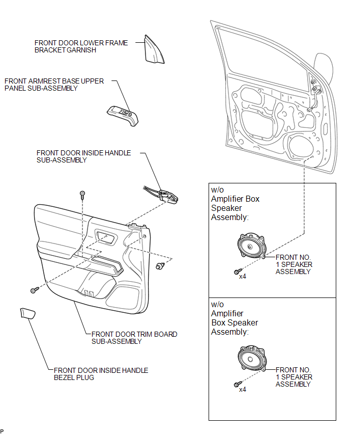
ILLUSTRATION

 Removal
REMOVAL
CAUTION / NOTICE / HINT
HINT:
Use the same procedure for the RH and LH sides.
The procedure listed below is for the LH side.
PROCEDURE
1. REMOVE FRONT DOOR LOWER FRAME B ...
Other materials:
Front Occupant Classification Sensor LH Collision Detection (B1785)
DESCRIPTION
DTC B1785 is set when the occupant detection ECU receives a collision detection
signal, which is sent by the occupant classification sensor front LH when an accident
occurs.
DTC B1785 is also set when the front seat with adjuster frame assembly RH is
subjected to a strong impact, ...
Air Outlet Damper Control Servo Motor Circuit (B1443/43)
DESCRIPTION
This No. 1 air conditioning radiator damper servo sub-assembly (for mode switching)
is controlled by the air conditioning amplifier assembly and moves the mode damper
to the desired position.
DTC No.
DTC Detection Condition
Trouble Area
...
Power outlet (120 VAC)∗
The power outlet can be used for electrical appliances.
Main switch
To use the power outlet, turn on the main switch.
The power supply starts a few seconds after the main switch is pressed.
Power outlet socket
Maximum available capacity of the power outlet
■ While the vehicle is being ...
