Toyota Tacoma (2015-2018) Service Manual: Components
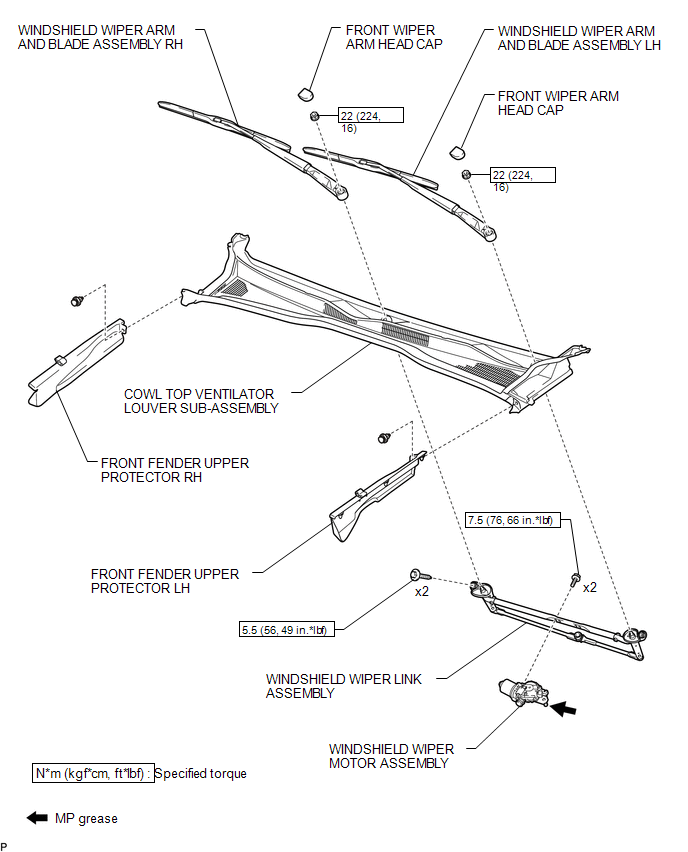
COMPONENTS
ILLUSTRATION

 On-vehicle Inspection
ON-VEHICLE INSPECTION
PROCEDURE
1. INSPECT FRONT WIPER MOTOR (for Driver Side)
Text in Illustration
*a
Matchmark
(a) Check the stop (park) position.
(b) Operate t ...
Other materials:
Lost Communication with ECM (U0100,U0142,U0155)
DESCRIPTION
DTC No.
DTC Detecting Condition
Trouble Area
U0100
No communication with ECM
CAN communication system
ECM
U0142
No communication with main body ECU
...
Disassembly
DISASSEMBLY
PROCEDURE
1. REMOVE HOOD BULGE ASSEMBLY (w/ Hood Bulge)
(a) Remove the 4 nuts.
(b) Disengage the clip from back side of the hood panel to remove the hood bulge
assembly together with the air intake guide.
2. REMOVE NO. 2 HOOD BU ...
System Diagram
SYSTEM DIAGRAM
Communication Table
Sender
Receiver
Signal
Line
*1: for Vacuum Brake Booster
*2: for Hydraulic Brake Booster
Millimeter Wave Radar Sensor Assembly
Forward Recognition Camera
...
