Toyota Tacoma (2015-2018) Service Manual: Power Source Circuit
DESCRIPTION
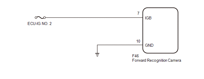
This circuit provides power to operate the forward recognition camera.
WIRING DIAGRAM
CAUTION / NOTICE / HINT
NOTICE:
Inspect the fuses for circuits related to this system before performing the following inspection procedure.
PROCEDURE
|
1. |
CHECK HARNESS AND CONNECTOR (POWER SOURCE VOLTAGE) |
|
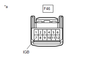
(a) Disconnect the forward recognition camera connector. |
|
(b) Measure the voltage according to the value(s) in the table below.
Standard Voltage:
|
Tester Connection |
Switch Condition |
Specified Condition |
|---|---|---|
|
F46-7 (IGB) - Body ground |
Ignition switch ON |
11 to 14 V |
(c) Connect the forward recognition camera connector.
| NG | .gif) |
REPAIR OR REPLACE HARNESS OR CONNECTOR |
|
.gif)
|
2. |
CHECK HARNESS AND CONNECTOR (FORWARD RECOGNITION CAMERA - BODY GROUND) |
|
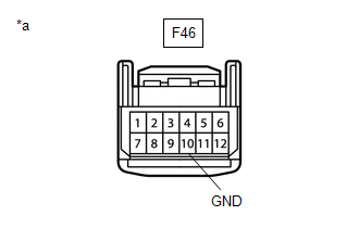
(a) Disconnect the forward recognition camera connector. |
|
(b) Measure the resistance according to the value(s) in the table below.
Standard Resistance:
|
Tester Connection |
Condition |
Specified Condition |
|---|---|---|
|
F46-10 (GND) - Body ground |
Always |
Below 1 Ω |
(c) Connect the forward recognition camera connector
| OK | |
PROCEED TO NEXT SUSPECTED AREA SHOWN IN PROBLEM SYMPTOMS TABLE |
| NG | |
REPAIR OR REPLACE HARNESS OR CONNECTOR |
 Front Camera Module Circuit (C1AA0)
DESCRIPTION
When an internal malfunction is detected in the forward recognition camera, DTC
C1AA0 is stored.
DTC No.
Detection Item
DTC Detection Condition
...
 Front Camera
...
Other materials:
Diagnosis System
DIAGNOSIS SYSTEM
1. DESCRIPTION
(a) The power window control system data can be read from the Data Link Connector
3 (DLC3) of the vehicle. When the system seems to be malfunctioning, use the Techstream
to check for malfunctions and perform repairs.
2. CHECK DLC3
(a) Check the DLC3 (See page ...
Fuel pump shut off system
To minimize the risk of fuel leakage when the engine stalls or an airbag inflates
upon collision, the fuel pump shut off system stops supplying fuel to the engine.
Follow the procedure below to restart the engine after the system is activated.
Turn the engine switch to the ACC
or LOCK positio ...
Components
COMPONENTS
ILLUSTRATION
ILLUSTRATION
ILLUSTRATION
ILLUSTRATION
ILLUSTRATION
ILLUSTRATION
ILLUSTRATION
ILLUSTRATION
ILLUSTRATION
ILLUSTRATION
...
