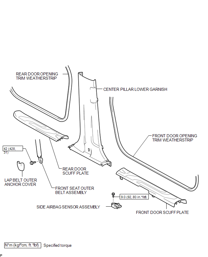
COMPONENTS
ILLUSTRATION
Related Tacoma materials
Refueling
Opening the fuel tank cap
Perform the following steps to open the fuel tank cap.
■ Before refueling the vehicle
Turn the engine switch off and ensure that all the doors and windows are closed.
■ Opening the fuel tank cap
Open the fuel filler door.
...
Front passenger occupant classification system
Your vehicle is equipped with a front passenger occupant classification system.
This system detects the conditions of the right front passenger seat and activates
or deactivates the devices for the front passenger.
1. SRS warning light
2. Front passenger’s seat belt reminder light
3. AIR ...
Emission inspection and maintenance (I/M) programs
Some states have vehicle emission inspection programs which include OBD (On
Board Diagnostics) checks. The OBD system monitors the operation of the emission
control system.
■ If the malfunction indicator lamp comes on
The OBD system determines that a problem exists somewhere in the emiss ...