Toyota Tacoma (2015-2018) Service Manual: Terminals Of Ecm
TERMINALS OF ECM
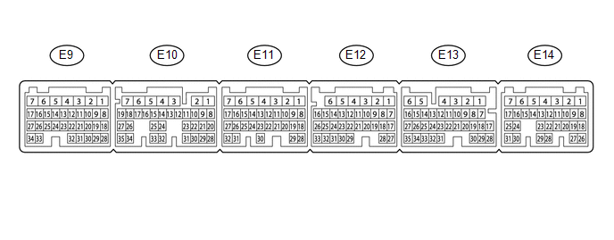
1. ECM
HINT:
The standard voltage between each pair of ECM terminals is shown in the table below. In the table, first follow the information under "Condition". Look under "Terminal No. (Symbol)" for the terminals to be inspected. The standard voltage between the terminals is shown under "Specified Condition".
Use the illustration above as a reference for the ECM terminals.
|
Terminal No. (Symbol) |
Wiring Color |
Terminal Description |
Condition |
Specified Condition |
|---|---|---|---|---|
|
E10-26 (THO1) - E9-23 (ETHW) |
P - BR |
No. 1 ATF temperature sensor signal |
No. 1 ATF temperature: 115°C (239°F) or higher |
Below 1.5 V |
|
E10-34 (THO2) - E9-23 (ETHW) |
L - BR |
No. 2 ATF temperature sensor signal |
No. 2 ATF temperature: 115°C (239°F) or higher |
Below 1.5 V |
|
E11-9 (SL1+) - E11-8 (SL1-) |
R - V |
Shift solenoid valve SL1 signal |
1st, 2nd, 3rd or 4th gear |
Pulse generation |
|
E11-11 (SLU+) - E11-10 (SLU-) |
P - L |
Shift solenoid valve SLU signal |
2nd, 3rd, 4th, 5th or 6th gear (Flex lock-up on) |
Pulse generation |
|
E11-13 (SLT+) - E11-12 (SLT-) |
LG - Y |
Shift solenoid valve SLT signal |
Engine idling |
Pulse generation |
|
E12-8 (SL4+) - E12-7 (SL4-) |
SB - BE |
Shift solenoid valve SL4 signal |
3rd or 5th gear |
Pulse generation |
|
E12-14 (SL3+) - E12-13 (SL3-) |
B - W |
Shift solenoid valve SL3 signal |
2nd or 6th gear |
Pulse generation |
|
E12-15 (SL) - E11-1 (E1) |
R - W-B |
Shift solenoid valve SL signal |
All gears |
11 to 14 V |
|
E12-17 (R) - E11-1 (E1) |
V - W-B |
R shift position switch signal |
Ignition switch ON and shift lever in R |
11 to 14 V |
|
Ignition switch ON and shift lever not in R |
Below 1 V |
|||
|
E12-18 (P) - E11-1 (E1) |
GR - W-B |
P shift position switch signal |
Ignition switch ON and shift lever in P |
11 to 14 V |
|
Ignition switch ON and shift lever not in P |
Below 1 V |
|||
|
E12-20 (SL2+) - E12-19 (SL2-) |
GR - BE |
Shift solenoid valve SL2 signal |
4th, 5th or 6th gear |
Pulse generation |
|
E12-26 (SP2B) - E11-1 (E1) |
G - W-B |
Power source for sensor (fixed voltage) |
Ignition switch ON |
11 to 14 V |
|
E12-27 (D) - E11-1 (E1) |
R - W-B |
D shift position switch signal |
Ignition switch ON and shift lever in D, S, "+" or "-" |
11 to 14 V |
|
Ignition switch ON and shift lever not in D, S, "+" or "-" |
Below 1 V |
|||
|
E12-28 (N) - E11-1 (E1) |
G - W-B |
N shift position switch signal |
Ignition switch ON and shift lever in N |
11 to 14 V |
|
Ignition switch ON and shift lever not in N |
Below 1 V |
|||
|
E12-31 (NTO) - E11-1 (E1) |
W - W-B |
Transmission revolution sensor (NT) signal |
Engine idling |
Pulse generation |
|
E12-32 (NTB) - E11-1 (E1) |
Y - W-B |
Power source for sensor (fixed voltage) |
Ignition switch ON |
11 to 14 V |
|
E12-33 (SP2O) - E11-1 (E1) |
L - W-B |
Transmission revolution sensor (SP2) signal |
Vehicle driving |
Pulse generation |
|
E13-7 (SFTD) - E11-1 (E1) |
R - W-B |
Down-shift position switch signal |
Ignition switch ON and shift lever in S |
11 to 14 V |
|
Ignition switch ON and shift lever in "-" (Down-shift) |
Below 1 V |
|||
|
E13-8 (SFTU) - E11-1 (E1) |
G - W-B |
Up-shift position switch signal |
Ignition switch ON and shift lever in S |
11 to 14 V |
|
Ignition switch ON and shift lever in "+" (Up-shift) |
Below 1 V |
|||
|
E13-12 (STA) - E11-1 (E1) |
Y - W-B |
Starter assembly signal |
Cranking |
6 V or higher |
|
E13-13 (NSW) - E11-1 (E1) |
V - W-B |
Park/neutral position switch signal |
Ignition switch ON and shift lever in P or N |
Below 1 V |
|
Ignition switch ON and shift lever not in P or N |
11 to 14 V |
|||
|
E13-16 (STP) - E11-1 (E1) |
P - W-B |
Stop light switch assembly signal |
Brake pedal depressed |
7.5 to 14 V |
|
Brake pedal released |
0 to 1.5 V |
|||
|
E13-24 (SPD) - E11-1 (E1) |
R - W-B |
Vehicle speed signal |
Vehicle being driven |
Pulse generation |
|
E13-27 (CANH) - E11-1 (E1) |
B - W-B |
CAN communication line |
Ignition switch ON |
Pulse generation |
|
E13-28 (PWMS) - E11-1 (E1) |
P - W-B |
Pattern select switch signal |
Ignition switch ON and pattern select switch pushed |
Below 1 V |
|
Ignition switch ON and pattern select switch not pushed |
11 to 14 V |
|||
|
E13-32 (S) - E11-1 (E1) |
P - W-B |
S shift position switch signal |
Ignition switch ON and shift lever in S, "+" or "-" |
11 to 14 V |
|
Ignition switch ON and shift lever not in S, "+" or "-" |
Below 1 V |
|||
|
E13-35 (CANL) - E11-1 (E1) |
W - W-B |
CAN communication line |
Ignition switch ON |
Pulse generation |
|
E14-2 (BATT) - E11-1 (E1) |
L - W-B |
Battery (for measuring battery voltage and for ECM memory) |
Always |
11 to 14 V |
 Problem Symptoms Table
PROBLEM SYMPTOMS TABLE
HINT:
Use the table below to help determine the cause of problem symptoms.
If multiple suspected areas are listed, the potential causes of the symptoms
are lis ...
 Check Mode Procedure
CHECK MODE PROCEDURE
1. DESCRIPTION
(a) Check mode has a higher sensitivity to malfunctions and can detect malfunctions
that normal mode cannot detect. Check mode can also detect all the malfuncti ...
Other materials:
Installation
INSTALLATION
PROCEDURE
1. INSTALL MAIN BODY ECU (MULTIPLEX NETWORK BODY ECU)
NOTICE:
Make sure that the connecting surfaces are free of foreign matter.
Do not touch the main body ECU (multiplex network body ECU) connector.
(a) Set the main body ECU (multiplex ...
If the engine will not start
If the engine still does not start after following the correct starting procedure
(→P. 141) or releasing the steering lock (→P. 142), confirm the following points.
■ The engine will not start even when the starter motor operates normally.
One of the following may be the cause o ...
Terminals Of Ecu
TERMINALS OF ECU
1. RADIO AND DISPLAY RECEIVER ASSEMBLY
Terminal No. (Symbol)
Wiring Color
Terminal Description
Condition
Specified Condition
R30-1 (FR+) - R30-7 (GND1)
LA-R - W-B
Sound signal (Front Ri ...
