Toyota Tacoma (2015-2018) Service Manual: Components
COMPONENTS
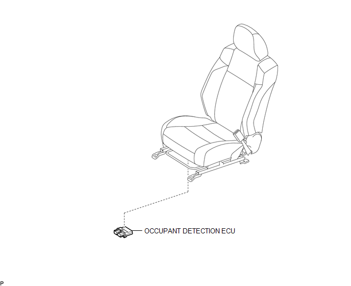
ILLUSTRATION

 On-vehicle Inspection
ON-VEHICLE INSPECTION
PROCEDURE
1. INSPECT OCCUPANT DETECTION ECU (for Vehicle not Involved in Collision)
(a) Perform a diagnostic system check (See page
).
2. INSPECT OCCUPANT DETECTION ECU (fo ...
Other materials:
Microphone Amplifier
Components
COMPONENTS
ILLUSTRATION
*A
w/o Sliding Roof
*B
w/ Sliding Roof
*1
TELEPHONE MICROPHONE ASSEMBLY
-
-
Removal
REMOVAL
PROCEDURE
1. REMOVE ROOF HEADLINING ASSEMBLY (for Double ...
Adjustment
ADJUSTMENT
PROCEDURE
1. INSPECT AND ADJUST CLUTCH PEDAL
(a) Fold back the floor carpet.
(b) Check that the pedal height is correct.
Text in Illustration
*a
Pedal Height Adjustment Point
*b
Push Rod Pla ...
Heater Circuit (C1AAE)
DESCRIPTION
The forward recognition camera controls the current supplied to the camera heater
(forward recognition hood).
If the forward recognition camera detects a malfunction in the camera heater
(forward recognition hood) circuit, DTC C1AAE is stored.
DTC No.
Detecti ...
