Toyota Tacoma (2015-2018) Service Manual: Components
COMPONENTS
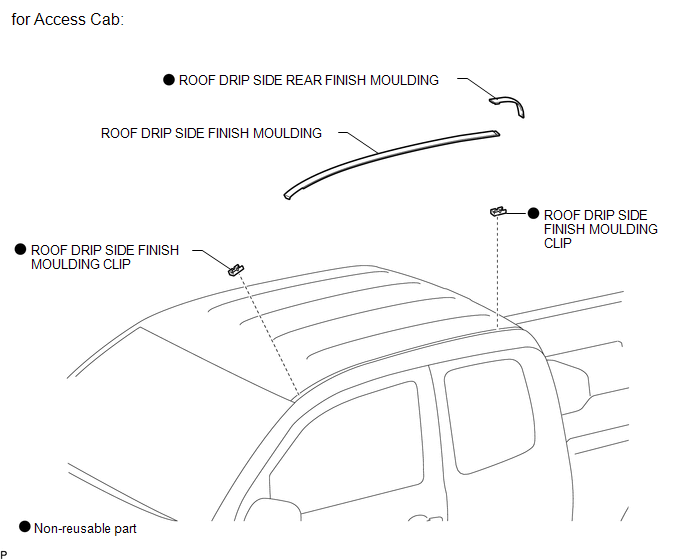
ILLUSTRATION
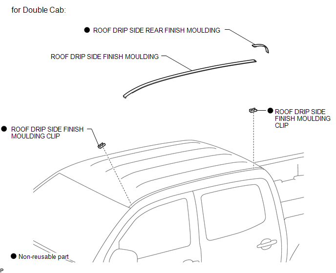
ILLUSTRATION

 Removal
REMOVAL
CAUTION / NOTICE / HINT
HINT:
Use the same procedures for the RH side and LH side.
The procedures listed below are for the LH side.
When removing the moulding, heat the vehi ...
Other materials:
On-vehicle Inspection
ON-VEHICLE INSPECTION
PROCEDURE
1. INSPECT DRIVE BELT
(a) Visually check the belt for defects, such as excessive wear and frayed cords.
If any defects are found, replace the drive belt.
HINT:
Replace the belt if there are any missing ribs.
2. BLEED POWER STEERING SYSTEM
(a) Check the fluid ...
Installation
INSTALLATION
PROCEDURE
1. INSTALL CAMSHAFT TIMING OIL CONTROL SOLENOID ASSEMBLY (for Intake Side of
Bank 1)
(a) Apply engine oil to a new O-ring and install it to the camshaft timing
oil control solenoid assembly in the locations shown in the illustration.
Text in Illustration ...
P/W Master Switch Communication Stop (B1206)
DESCRIPTION
This DTC is stored when LIN communication between the power window regulator
master switch assembly and main body ECU (multiplex network body ECU) stops for
10 seconds or more.
DTC No.
DTC Detection Condition
Trouble Area
B1206
...
