Toyota Tacoma (2015-2018) Service Manual: Components
COMPONENTS
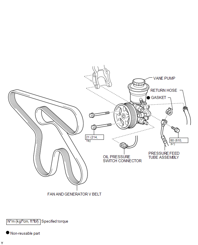
ILLUSTRATION
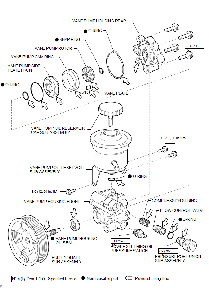
ILLUSTRATION

 Disassembly
DISASSEMBLY
PROCEDURE
1. FIX VANE PUMP
(a) Using SST, fix the vane pump assembly in a vise.
SST: 09630-00014
09631-00132
NOTICE:
When using a vise, do not overtighten it.
2. REMOVE VANE PUMP ...
Other materials:
AVC-LAN Circuit
DESCRIPTION
Each unit of the navigation system connected to the AVC-LAN (communication bus)
transfers the switch signals using the AVC-LAN.
If a short to +B or short to ground occurs in the AVC-LAN, the navigation system
will not function normally because communication is not possible.
WIRING ...
Sleep Operation Failure of Occupant Classification ECU (B1796)
DESCRIPTION
During sleep mode, the occupant detection ECU monitors the condition of each
sensor while the ignition switch is off. In this mode, if the occupant detection
ECU detects an internal malfunction, DTC B1796 is set.
DTC No.
DTC Detections Conditions
Tr ...
On-vehicle Inspection
ON-VEHICLE INSPECTION
PROCEDURE
1. INSPECT INSTRUMENT PANEL PASSENGER AIRBAG ASSEMBLY WITHOUT DOOR (for Vehicle
not Involved in Collision)
(a) Perform a diagnostic system check (See page
).
(b) With the instrument panel passenger airbag ...
