Toyota Tacoma (2015-2018) Service Manual: Tail Gate Protector
Components
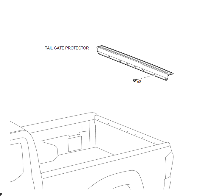
COMPONENTS
ILLUSTRATION
Removal
REMOVAL
PROCEDURE
1. REMOVE TAIL GATE PROTECTOR
|
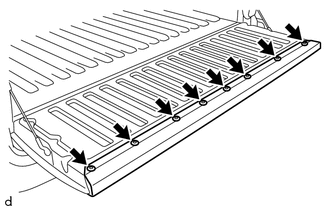
(a) Using a T30 "TORX" socket wrench, remove the 8 screws. |
|
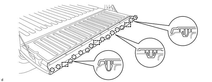
(b) Disengage the 14 claws and 3 guides to remove the tail gate protector.
Installation
INSTALLATION
PROCEDURE
1. INSTALL TAIL GATE PROTECTOR
(a) Engage the 3 guides and 14 claws to install the tail gate protector.
(b) Using a T30 "TORX" socket wrench, install the 8 screws.
 Side Moulding
Components
COMPONENTS
ILLUSTRATION
ILLUSTRATION
Removal
REMOVAL
CAUTION / NOTICE / HINT
HINT:
Use the same procedure for the RH side and LH side.
The following procedure is ...

Other materials:
Rear Differential Lock Position SW Stuck ON (P17BC)
DESCRIPTION
This DTC is output when an ON malfunction of the differential lock indicator
switch is detected.
DTC No.
Detection Item
DTC Detection Condition
Trouble Area
P17BC
Rear Differential Lock Position SW Stuck ON
...
Sound of Portable Player cannot be Heard from Speakers or Sound is Low
PROCEDURE
1.
CHECK PORTABLE PLAYER SETTINGS
(a) Check the portable player settings.
(1) Check that the volume is not set to "0".
(2) Check that the mute is off.
(b) Check that the sound of the portable player can be heard from the speakers.
OK:
Sound ...
On-vehicle Inspection
ON-VEHICLE INSPECTION
PROCEDURE
1. CHECK BATTERY CONDITION
NOTICE:
If the battery is weak or if the engine is difficult to start, recharge the battery
and perform inspections again before returning the vehicle to the customer.
(a) Check the battery for damage or deformation. If severe damage, ...
