Toyota Tacoma (2015-2018) Service Manual: Components
COMPONENTS
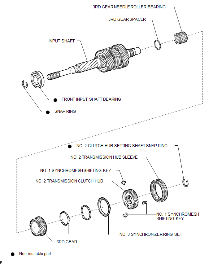
ILLUSTRATION
ILLUSTRATION
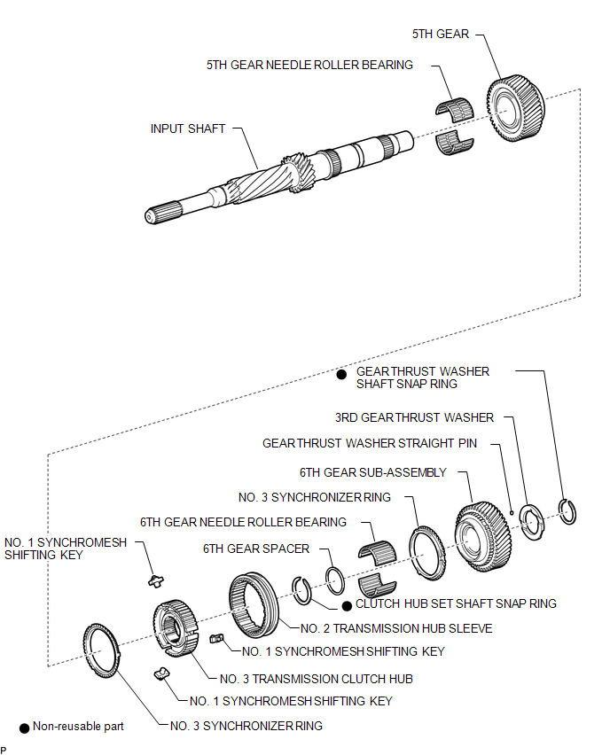
 Input Shaft
...
 Disassembly
DISASSEMBLY
PROCEDURE
1. INSPECT 3RD GEAR THRUST CLEARANCE
(a) Using a dial indicator, measure the 3rd gear thrust clearance.
Standard clearance:
0.200 to 0.490 mm (0.0079 to 0.01 ...
Other materials:
Stereo Component Amplifier
Components
COMPONENTS
ILLUSTRATION
ILLUSTRATION
Removal
REMOVAL
PROCEDURE
1. PRECAUTION
NOTICE:
After turning the ignition switch off, waiting time may be required before disconnecting
the cable from the negative (-) battery terminal. Therefore, make sure to read the
disconnecti ...
List of storage features
Glove box
Overhead console (Access Cab and
Double Cab models)
Bottle holders
Auxiliary boxes
Front console box (separated type
front seat only)
Cup holders
CAUTION
■Items that should not be left in the storage spaces
Do not leave glasses, lighters or spray cans in the stora ...
Touch Panel Switch does not Function
PROCEDURE
1.
CHECK MULTI-DISPLAY
(a) Check if there is any foreign matter caught between the display and exterior
frame of the multi-display.
OK:
No foreign matter is caught between the display and exterior frame of the multi-display.
HINT:
If there is foreig ...
