Toyota Tacoma (2015-2018) Service Manual: Terminals Of Ecu
TERMINALS OF ECU
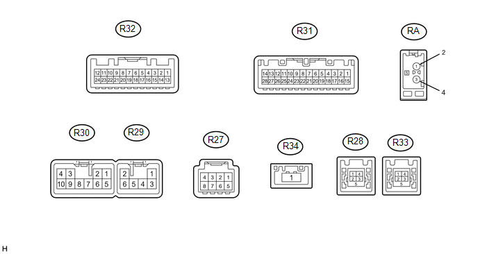
1. RADIO AND DISPLAY RECEIVER ASSEMBLY
|
Terminal No. (Symbol) |
Wiring Color |
Terminal Description |
Condition |
Specified Condition |
|---|---|---|---|---|
|
R30-1 (FR+) - R30-7 (GND1) |
LA-R - W-B |
Sound signal (Front Right) |
Audio system playing |
A waveform synchronized with sounds is output |
|
R30-2 (FL+) - R30-7 (GND1) |
LA-B - W-B |
Sound signal (Front Left) |
Audio system playing |
A waveform synchronized with sounds is output |
|
R30-3 (ACC1) - R30-7 (GND1) |
GR - W-B |
Power source (ACC) |
Ignition switch off |
Below 1 V |
|
Ignition switch ACC |
11 to 14 V |
|||
|
R30-4 (+B1) - R30-7 (GND1) |
W - W-B |
Power source (+B) |
Always |
11 to 14 V |
|
R30-5 (FR-) - R30-7 (GND1) |
LA-G - W-B |
Sound signal (Front Right) |
Audio system playing |
A waveform synchronized with sounds is output |
|
R30-6 (FL-) - R30-7 (GND1) |
LA-W - W-B |
Sound signal (Front Left) |
Audio system playing |
A waveform synchronized with sounds is output |
|
R30-7 (GND1) - Body ground |
W-B - Body ground |
Ground |
Always |
Below 1 V |
|
R30-10 (ILL+) - R30-7 (GND1) |
G - W-B |
Illumination signal |
Light control switch off |
Below 1 V |
|
Light control switch in tail or head position |
11 to 14 V |
|||
|
R29-1 (RR+) - R30-7 (GND1) |
L - W-B |
Sound signal (Rear Right)*2 |
Audio system playing |
A waveform synchronized with sounds is output |
|
R29-2 (RL+) - R30-7 (GND1) |
W - W-B |
Sound signal (Rear Left)*2 |
Audio system playing |
A waveform synchronized with sounds is output |
|
R29-3 (RR-) - R30-7 (GND1) |
LG - W-B |
Sound signal (Rear Right)*2 |
Audio system playing |
A waveform synchronized with sounds is output |
|
R29-5 (ILL-) - R30-7 (GND1) |
BE - W-B |
Illumination (rheostat) signal |
Light control switch off and rheostat switch position medium |
Below 1 V |
|
Light control switch in tail or head position |
Pulse generation |
|||
|
R29-6 (RL-) - R30-7 (GND1) |
B - W-B |
Sound signal (Rear Right)*2 |
Audio system playing |
A waveform synchronized with sounds is output |
|
R31-1 (IG) - R30-7 (GND1) |
LG - W-B |
Power source (IG) |
Ignition switch off |
Below 1 V |
|
Ignition switch ON |
11 to 14 V |
|||
|
R31-2 (REV) - R30-7 (GND1) |
GR - W-B |
Reverse signal |
Ignition switch ON, shift lever not in R |
Below 1 V |
|
Ignition switch ON, shift lever in R |
11 to 14 V |
|||
|
R31-4 (MACC) - R30-7 (GND1) |
R - W-B |
Microphone power supply |
Ignition switch off |
Below 1 V |
|
Ignition switch ON |
4 to 6 V |
|||
|
R31-5 (MIN+) - R30-7 (GND1) |
G - W-B |
Microphone voice signal |
"Bluetooth" hands-free function on |
A waveform synchronized with sounds is output |
|
R31-6 (SNS2) - R30-7 (GND1) |
W - W-B |
Microphone connection detection signal |
Always |
Below 1 V |
|
R31-9 (CANH) |
V |
CAN communication signal |
- |
- |
|
R31-10 (CANL) |
W |
CAN communication signal |
- |
- |
|
R31-11 (AGND) - Body ground |
Shielded - Body ground |
Shield ground |
Always |
Below 1 V |
|
R31-15 (PKB) - R30-7 (GND1) |
Y - W-B |
Parking brake switch signal |
Parking brake switch off |
Below 1 V |
|
Parking brake switch on |
11 to 14 V |
|||
|
R31-18 (SGND) - Body ground |
Shielded - Body ground |
Shield ground |
Always |
Below 1 V |
|
R31-19 (MIN-) - R30-7 (GND1) |
B - W-B |
Microphone voice signal |
"Bluetooth" hands-free function on |
A waveform synchronized with sounds is output |
|
R31-17 (SPD) - R30-7 (GND1) |
V - W-B |
Vehicle Speed signal |
Ignition switch ON Wheel being rotated |
Pulse generation |
|
R31-21 (SW1) - R30-7 (GND1)*1 |
V - W-B |
Steering pad switch signal |
No switch pushed |
2.97 to 3.56 V |
|
Up switch pushed |
0.27 to 0.35 V |
|||
|
Down switch pushed |
0.86 to 1.03 V |
|||
|
Volume+ switch pushed |
1.51 to 1.79 V |
|||
|
Volume- switch pushed |
2.22 to 2.66 V |
|||
|
R31-22 (SW2) - R30-7 (GND1)*1 |
Y - W-B |
Steering pad switch signal |
No switch pushed |
2.97 to 3.56 V |
|
MODE/HOLD switch pushed |
0.27 to 0.35 V |
|||
|
On hook switch pushed |
0.86 to 1.03 V |
|||
|
Off hook switch pushed |
1.51 to 1.79 V |
|||
|
Voice switch pushed |
2.22 to 2.66 V |
|||
|
R31-23 (SWG) - R30-7 (GND1)*1 |
SB - W-B |
Steering pad switch ground |
Always |
Below 1 V |
|
R31-25 (ADPG) - R30-7 (GND1) |
W-B - W-B |
External device connection detection signal |
External device connected |
Below 1 V |
|
R31-26 (VAR+) - R30-7 (GND1) |
W - W-B |
Sound signal (Right) |
External device playing (When stereo jack used) |
A waveform synchronized with sounds is output |
|
R31-27 (VA-) - R30-7 (GND1) |
R - W-B |
Ground |
Always |
Below 1 V |
|
R31-28 (VAL+) - R30-7 (GND1) |
B - W-B |
Sound signal (Left) |
External device playing (When stereo jack used) |
A waveform synchronized with sounds is output |
|
R32-3 (CNH1) |
B |
Local bus communication signal |
- |
- |
|
R32-4 (CNL1) |
W |
Local bus communication signal |
- |
- |
|
R32-24 (V-) - R30-7 (GND1) |
W - W-B |
Ground |
Always |
Below 1 V |
|
R32-12 (V+) - R32-24 (V-) |
R - W |
Video signal |
Ignition switch ON, shift lever in R |
Pulse generation (See waveform 1) |
|
Ignition switch ON, shift lever in R, screen blacked out by covering camera lens |
Pulse generation (See waveform 2) |
|||
|
R32-23 (CGND) - Body ground |
Shield - Body ground |
Shield ground |
Always |
Below 1 V |
|
R32-11 (CA+) - R30-7 (GND1) |
B - W-B |
Power source |
Ignition switch ON, shift lever in R |
5.5 to 7.05 V |
|
R27-3 (ACC2) - R30-7 (GND1)*1 |
Y - W-B |
Power source (ACC) |
Ignition switch off |
Below 1 V |
|
Ignition switch ACC |
11 to 14 V |
|||
|
R27-4 (+B2) - R30-7 (GND1)*1 |
R - W-B |
Power source (+B) |
Always |
11 to 14 V |
|
R27-8 (GND2) - Body ground*1 |
B - Body ground |
Ground |
Always |
Below 1 V |
|
R28-1 (UPO) |
- |
Power source |
- |
- |
|
R28-2 (UDO-) |
- |
Data signal |
- |
- |
|
R28-3 (UDO+) |
- |
Data signal |
- |
- |
|
R28-4 (UESG) |
- |
Ground |
- |
- |
|
R33-2 (US4-)*1 |
- |
Data signal |
- |
- |
|
R33-3 (US4+)*1 |
- |
Data signal |
- |
- |
|
R33-4 (UGO4)*1 |
- |
Ground |
- |
- |
|
R33-5 (USG4)*1 |
- |
Shield ground |
- |
- |
|
R34-1 (LVDS)*1 |
B |
LVDS communication signal |
- |
- |
|
RA-5 (ANT+) - R30-7 (GND1) |
B - W-B |
Power source of antenna |
Ignition switch ACC Radio switch on and AM or FM |
11 to 14 V |
- *1: w/ SDARS System
- *2: for 6 Speakers
(a) Using an oscilloscope, check the waveform.
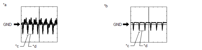
(1) Waveform 1 (Reference)
|
Item |
Content |
|---|---|
|
Terminal No. (Symbol) |
R32-12 (V+) - R32-24 (V-) |
|
Tool Setting |
200 mV/DIV., 50 ÎĽsec./DIV. |
|
Condition |
Ignition switch ON, shift lever in R |
HINT:
The video waveform changes according to the image sent by the rear television camera assembly.
(2) Waveform 2 (Reference)
|
Item |
Content |
|---|---|
|
Terminal No. (Symbol) |
R32-12 (V+) - R32-24 (V-) |
|
Tool Setting |
200 mV/DIV., 50 ÎĽsec./DIV. |
|
Condition |
Ignition switch ON, shift lever in R, screen blacked out by covering camera lens |
HINT:
The video waveform changes according to the image sent by the rear television camera assembly.
Text in Illustration|
*a |
Waveform 1 |
|
*b |
Waveform 2 |
|
*c |
Synchronized Signal |
|
*d |
Video Waveform |
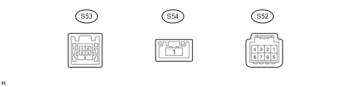
2. STEREO COMPONENT TUNER ASSEMBLY (w/ SDARS System)
|
Terminal No. (Symbol) |
Wiring Color |
Terminal Description |
Condition |
Specified Condition |
|---|---|---|---|---|
|
S52-3 (ACC2) - S52-8 (GND2) |
Y - B |
Power source (ACC) |
Ignition switch off |
Below 1 V |
|
Ignition switch ACC |
11 to 14 V |
|||
|
S52-4 (+B2) - S52-8 (GND2) |
R - B |
Power source (+B) |
Always |
11 to 14 V |
|
S52-8 (GND2) - Body ground |
B - Body ground |
Ground |
Always |
Below 1 V |
|
S53-1 (USV4) |
- |
Power source |
- |
- |
|
S53-2 (US4-) |
- |
Data signal |
- |
- |
|
S53-3 (US4+) |
- |
Data signal |
- |
- |
|
S53-4 (UGO4) |
- |
Ground |
- |
- |
|
S53-5 (USG4) |
B |
Shield ground |
- |
- |
|
S54-1 (LVDS) |
- |
LVDS communication signal |
- |
- |
 Problem Symptoms Table
PROBLEM SYMPTOMS TABLE
NOTICE:
After replacing the stereo component tuner assembly of vehicles subscribed to
pay-type satellite radio broadcasts, XM radio ID registration is necessary (w/ SDARS
...
 Dtc Check / Clear
DTC CHECK / CLEAR
1. CHECK DTC (CHECK USING TECHSTREAM)
(a) Connect the Techstream to the DLC3.
(b) Turn the ignition switch to ON.
(c) Turn the Techstream on.
(d) Enter the following menus: Body ...
Other materials:
Removal
REMOVAL
PROCEDURE
1. REMOVE MILLIMETER WAVE RADAR WIRE
(a) for Type A:
(1) Disconnect the 2 connectors.
(2) Using a clip remover, disengage the 4 clamps to remove the millimeter
wave radar wire.
(b) for Type B:
(1) Disc ...
Removal
REMOVAL
PROCEDURE
1. REMOVE FUEL PUMP ASSEMBLY (for High Pressure)
(See page )
2. REMOVE NO. 2 FUEL PIPE SUB-ASSEMBLY
(a) Loosen the 2 union nuts and remove the No. 2 fuel pipe sub-assembly from
the fuel delivery pipe RH and fuel delivery pipe sub-assembly LH.
Text in Illustration
...
Master Cylinder Pressure Sensor Output Malfunction (Test Mode DTC) (C1281,...,C1458)
DESCRIPTION
DTC Code
DTC Detection Condition
Trouble Area
C1281
Stored only during test mode.
Master cylinder pressure sensor circuit
Skid control ECU, master cylinder pressure sensor (master cylinder
s ...
