Toyota Tacoma (2015-2018) Service Manual: Front Evaporator Temperature Sensor
Inspection
INSPECTION
PROCEDURE
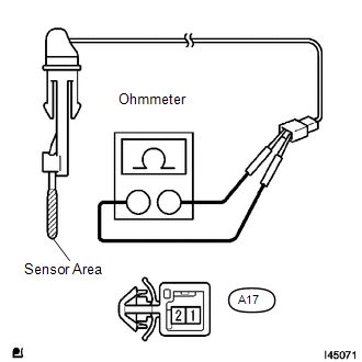
1. INSPECT COOLER THERMISTOR SENSOR
(a) Check the resistance.
|
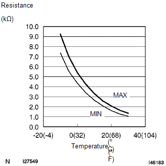
(1) Measure the resistance and check the results in accordance with the values in the table below. Standard:
If the result is not as specified, replace the cooler thermistor sensor. NOTICE:
HINT: As the temperature increases, the resistance decreases (see the graph on the left). |
|
 Front Blower Resistor
Inspection
INSPECTION
PROCEDURE
1. INSPECT BLOWER RESISTOR
(a) Check the resistance.
(1) Measure the resistance according to the value(s) in the table below.
Standard Resistance ...
 Heater Relay
Inspection
INSPECTION
PROCEDURE
1. INSPECT HEATER RELAY
(a) Check the resistance.
(1) Using an ohmmeter, measure the resistance between each terminal.
Standard:
...
Other materials:
Removal
REMOVAL
PROCEDURE
1. REMOVE FRONT FENDER SEAL RH
HINT:
Use the same procedure as for the LH side (See page
).
2. REMOVE V-BANK COVER SUB-ASSEMBLY
3. REMOVE AIR CLEANER CAP AND HOSE
4. REMOVE ENGINE OIL LEVEL DIPSTICK GUIDE
(a) Remove the engine oil level dipstick.
(b) Di ...
Problem Symptoms Table
PROBLEM SYMPTOMS TABLE
HINT:
Use the table below to help determine the cause of problem symptoms.
If multiple suspected areas are listed, the potential causes of the symptoms
are listed in order of probability in the "Suspected Area" column of the
table. Check each sy ...
Clearance Warning ECU Communication Stop Mode
DESCRIPTION
Detection Item
Symptom
Trouble Area
Clearance Warning ECU Communication Stop Mode
Either Condition is met:
Communication stop for "Clearance Warning (Intuitive Parking
Assist1)" is indicated on th ...
