Toyota Tacoma (2015-2018) Service Manual: Components
COMPONENTS
ILLUSTRATION
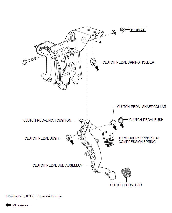
 Clutch Pedal
...
 Removal
REMOVAL
PROCEDURE
1. REMOVE CLUTCH MASTER CYLINDER ASSEMBLY
(See page )
2. REMOVE TURN OVER SPRING SEAT COMPRESSION SPRING
(a) Remove the compression spring.
...
Other materials:
Inspection
INSPECTION
PROCEDURE
1. INSPECT REAR NO. 2 POWER WINDOW REGULATOR SWITCH ASSEMBLY
*a
Component without harness connected
(Rear No. 2 Power Window Regulator Switch Assembly)
*b
Pull (Close)
*c
Push (Open)
...
Components
COMPONENTS
ILLUSTRATION
*A
for Double Cab
*B
for Access Cab
*1
AUTO HIGH BEAM SWITCH
*2
COWL SIDE TRIM BOARD LH
*3
FRONT DOOR SCUFF PLATE LH
*4
HOOD LOC ...
Removal
REMOVAL
PROCEDURE
1. PRECAUTION
CAUTION:
Be sure to read Precaution thoroughly before servicing (See page
).
NOTICE:
After turning the ignition switch off, waiting time may be required before disconnecting
the cable from the negative (-) battery terminal. Therefore, make sure to read the
...
