Toyota Tacoma (2015-2018) Service Manual: Removal
REMOVAL
PROCEDURE
1. REMOVE CLUTCH MASTER CYLINDER ASSEMBLY
(See page .gif) )
)
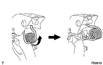
2. REMOVE TURN OVER SPRING SEAT COMPRESSION SPRING
|
(a) Remove the compression spring. |
|
3. REMOVE CLUTCH PEDAL SUB-ASSEMBLY
|
(a) Remove the bolt and nut. |
|
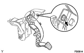
(b) Remove the clutch pedal sub-assembly from the clutch pedal support.
4. REMOVE CLUTCH PEDAL SPRING HOLDER
|
(a) Remove the clutch pedal spring holder from the clutch pedal support. |
|
5. REMOVE CLUTCH PEDAL PAD
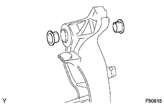
6. REMOVE CLUTCH PEDAL BUSH
|
(a) Remove the 2 bushes from the clutch pedal sub-assembly. |
|
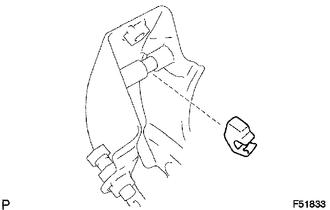
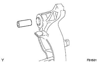
7. REMOVE CLUTCH PEDAL SHAFT COLLAR
|
(a) Remove the clutch pedal shaft collar from the clutch pedal sub-assembly. |
|
8. REMOVE CLUTCH PEDAL NO.1 CUSHION
|
(a) Using needle-nose pliers, remove the clutch pedal No. 1 cushion from the clutch pedal sub-assembly. |
|

 Components
COMPONENTS
ILLUSTRATION
...
 Adjustment
ADJUSTMENT
PROCEDURE
1. INSPECT AND ADJUST CLUTCH PEDAL
(a) Fold back the floor carpet.
(b) Check that the pedal height is correct.
Text in Illustration
*a
...
Other materials:
Fuel Receiver Gauge Malfunction
DESCRIPTION
The meter CPU uses the fuel sender gauge assembly to determine the level of the
fuel in the fuel tank. The resistance of the fuel sender gauge will vary between
approximately 13.5 Ω with the float at the full position, and 414.5 Ω with the float
at the empty position. The meter ...
Parts Location
PARTS LOCATION
ILLUSTRATION
*A
w/ Fog Light
*B
w/ Automatic High Beam System
*C
for Manual Transmission
-
-
*1
HEADLIGHT ASSEMBLY LH
*2
HEADLIGHT ASSEMB ...
How To Proceed With Troubleshooting
CAUTION / NOTICE / HINT
HINT:
*: Use the Techstream.
PROCEDURE
1.
VEHICLE BROUGHT TO WORKSHOP
NEXT
2.
CUSTOMER PROBLEM ANALYSIS CHECK
HINT:
In troubleshooti ...
