Toyota Tacoma (2015-2018) Service Manual: Components
COMPONENTS
ILLUSTRATION
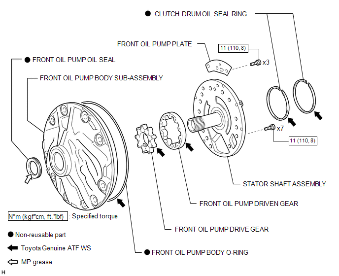
 Oil Pump
...
 Disassembly
DISASSEMBLY
PROCEDURE
1. REMOVE FRONT OIL PUMP BODY O-RING
(a) Remove the front oil pump body O-ring from the oil pump assembly.
2. SECURE OIL ...
Other materials:
On-vehicle Inspection
ON-VEHICLE INSPECTION
PROCEDURE
1. INSPECT SPEEDOMETER
(a) Check speedometer operation.
NOTICE:
The meter ECU receives the vehicle speed signal from the skid control
ECU via CAN communication. Therefore, perform the following inspection referring
to values on the Data List of th ...
Interior Light Auto Cut Circuit
DESCRIPTION
When the battery saving control operates, the main body ECU (multiplex network
body ECU) controls the operation of the DOME CUT relay, that is built in to the
driver side junction block, to turn off the interior lights.
WIRING DIAGRAM
CAUTION / NOTICE / HINT
NOTICE:
In ...
Vehicle Speed Signal Circuit between Stereo Component Amplifier and Combination
Meter
DESCRIPTION
The stereo component amplifier assembly receives a vehicle speed signal from
the combination meter assembly to control the ASL function.
HINT:
A voltage of 12 V or 5 V is output from each ECU and then input to the
combination meter assembly. The signal is changed to a pu ...
