Toyota Tacoma (2015-2018) Service Manual: Removal
REMOVAL
PROCEDURE
1. REMOVE AIR CONDITIONING CONTROL ASSEMBLY (for Automatic Air Conditioning System)
(See page .gif) )
)
2. REMOVE INTEGRATION PANEL SUB-ASSEMBLY (for Manual Cooler System)
(See page )
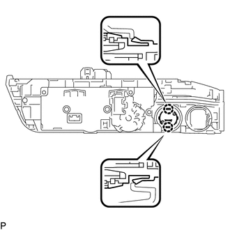
3. REMOVE TRANSFER POSITION SWITCH
|
(a) Detach the 2 claws to remove the transfer position switch. |
|
 On-vehicle Inspection
ON-VEHICLE INSPECTION
PROCEDURE
1. INSPECT INDICATOR LIGHT
(a) Inspect the 4HI Indicator Light:
(1) Start the engine.
(2) Change the 4WD control switch from 2WD to 4H.
(3) Check the 4HI indicato ...
 Installation
INSTALLATION
PROCEDURE
1. INSTALL TRANSFER POSITION SWITCH
(a) Attach the 2 claws to install the transfer position switch.
2. INSTALL AIR CONDITIONING CONTROL ASSEMBLY (for Automatic Air Condition ...
Other materials:
Diagnostic Trouble Code Chart
DIAGNOSTIC TROUBLE CODE CHART
HINT:
If a trouble code is displayed during the DTC check, inspect the trouble areas
listed for that code. For details of the code, refer to the "See page" below.
Lighting system
DTC Code
Detection Item
See page
...
Electronic Circuit Inspection Procedure
ELECTRONIC CIRCUIT INSPECTION PROCEDURE
1. BASIC INSPECTION
(a) WHEN MEASURING RESISTANCE OF ELECTRONIC PARTS
(1) Unless otherwise stated, all resistance measurements should be made at an
ambient temperature of 20°C (68°F). Resistance measurements may be inaccurate if
measured at high tempe ...
Dtc Check / Clear
DTC CHECK / CLEAR
1. CHECK DTC
(a) Connect the Techstream to the DLC3.
(b) Turn the ignition switch to ON.
(c) Turn the Techstream on.
(d) Enter the following menus: Body Electrical / Trouble Codes.
(e) Check DTCs and then write them down.
HINT:
Refer to the Techstream operator's manual ...
