Toyota Tacoma (2015-2018) Service Manual: Reassembly
REASSEMBLY
PROCEDURE
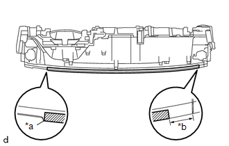
1. INSTALL INSTRUMENT PANEL CUSHION
|
(a) Install a new instrument panel cushion as shown in the illustration. Text in Illustration
HINT:
|
|
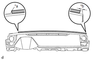
2. INSTALL NO. 4 INSTRUMENT PANEL CUSHION
|
(a) Install a new No. 4 instrument panel cushion as shown in the illustration. Text in Illustration
HINT:
|
|
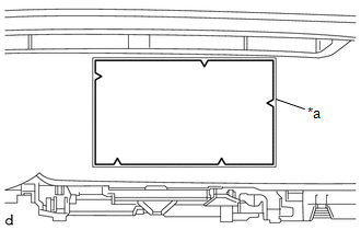
3. INSTALL NO. 2 INSTRUMENT PANEL CUSHION
|
(a) Align a new No. 2 instrument panel cushion with the silencer markings on the instrument panel sub-assembly and install the No. 2 instrument panel cushion using hot-melt glue. Text in Illustration
|
|
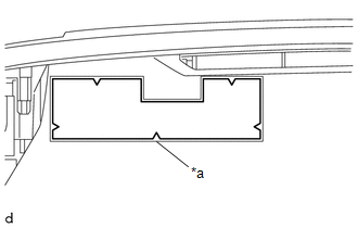
4. INSTALL NO. 1 INSTRUMENT PANEL CUSHION
|
(a) Align a new No. 1 instrument panel cushion with the silencer markings on the instrument panel sub-assembly and install the No. 1 instrument panel cushion using hot-melt glue. Text in Illustration
|
|
5. INSTALL NO. 1 METER HOOD RETAINER
HINT:
Use the same procedure as for the opposite side.
|
(a) Engage the guide to install the No. 1 meter hood retainer. |
|
.png)
(b) Install the screw <D>.
6. INSTALL NO. 1 INSTRUMENT PANEL PIN
HINT:
Use the same procedure as for the opposite side.
|
(a) Engage the guide to install the No. 1 instrument panel pin. |
|
.png)
(b) Install the screw <F>.
7. INSTALL INSTRUMENT PANEL PASSENGER WITHOUT DOOR AIRBAG ASSEMBLY
.gif)
8. INSTALL ANTENNA CORD SUB-ASSEMBLY
9. INSTALL NAVIGATION ANTENNA ASSEMBLY (w/ Navigation System)
10. INSTALL NETWORK GATEWAY ECU
11. INSTALL NO. 1 INSTRUMENT PANEL REGISTER SUB-ASSEMBLY
|
(a) Engage the 3 guides and 6 claws to install the No. 1 instrument panel register sub-assembly. |
|
.png)
12. INSTALL DEFROSTER NOZZLE ASSEMBLY
|
(a) Engage the 3 guides to install the defroster nozzle assembly. |
|
.png)
(b) Install the 3 screws <F>.
13. INSTALL SIDE NO. 2 DEFROSTER NOZZLE DUCT
|
(a) Engage the 2 claws and 2 guides to install the No. 2 defroster nozzle duct. |
|
.png)
(b) Install the 2 screws <F>.
14. INSTALL SIDE NO. 1 DEFROSTER NOZZLE DUCT
|
(a) Engage the 2 claws and 2 guides to install the No. 1 defroster nozzle duct. |
|
.png)
(b) Install the 2 screws <F>.
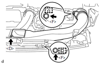
15. INSTALL NO. 2 HEATER TO REGISTER DUCT
|
(a) Engage the 2 guides to install the No. 2 heater to register duct. |
|
.png)
(b) Install the 2 screws <F> and screw <D>.
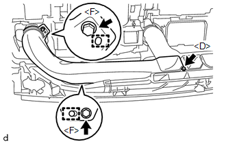
16. INSTALL NO. 3 HEATER TO REGISTER DUCT
|
(a) Engage the 2 guides to install the No. 3 heater to register duct. |
|
(b) Install the 2 screws <F> and screw <D>.
17. INSTALL NO. 1 HEATER TO REGISTER DUCT
|
(a) Engage the 2 guides to install the No. 1 heater to register duct. |
|
(b) Install the 2 screws <F> and screw <D>.
 Installation
INSTALLATION
PROCEDURE
1. INSTALL INSTRUMENT PANEL SUB-ASSEMBLY
(a) Engage the 5 guides to install the instrument panel sub-assembly.
(b) Engage the clamps and connect the connectors.
(c) Insta ...
 Lighting
...
Other materials:
Components
COMPONENTS
ILLUSTRATION
ILLUSTRATION
ILLUSTRATION
ILLUSTRATION
ILLUSTRATION
...
Removal
REMOVAL
CAUTION / NOTICE / HINT
NOTICE:
Release the vacuum from booster by depressing the brake pedal several times.
Then remove the brake master cylinder from brake booster.
PROCEDURE
1. PRECAUTION
NOTICE:
After turning the ignition switch off, waiting time may be required before disconnect ...
Installation
INSTALLATION
PROCEDURE
1. INSTALL MAIN BODY ECU (MULTIPLEX NETWORK BODY ECU)
NOTICE:
Make sure that the connecting surfaces are free of foreign matter.
Do not touch the main body ECU (multiplex network body ECU) connector.
(a) Set the main body ECU (multiplex ...
