Toyota Tacoma (2015-2018) Service Manual: Check Bus 3 Lines for Short Circuit
DESCRIPTION
There may be a short circuit between the CAN main bus lines and/or CAN branch lines when the resistance between terminals 6 (CA3H) and 21 (CA3L) of the central gateway ECU (network gateway ECU) is below 54 Ω.
|
Detection Item |
Trouble Area |
|---|---|
|
Resistance between terminals 6 (CA3H) and 21 (CA3L) of central gateway ECU (network gateway ECU) is below 54 Ω. |
|
- *1: for Navigation Receiver Type
- *2: for Radio and Display Type
WIRING DIAGRAM
.png)
CAUTION / NOTICE / HINT
CAUTION:
When performing the confirmation driving pattern, obey all speed limits and traffic laws.
NOTICE:
- Because the order of diagnosis is important to allow correct diagnosis,
make sure to begin troubleshooting using How to Proceed with Troubleshooting
when CAN communication system related DTCs are output.
Click here
.gif)
- Before measuring the resistance of the CAN bus, turn the ignition switch off and leave the vehicle for 1 minute or more without operating the key or any switches, or opening or closing the doors. After that, disconnect the cable from the negative (-) battery terminal and leave the vehicle for 1 minute or more before measuring the resistance.
- After turning the ignition switch off, waiting time may be required
before disconnecting the cable from the negative (-) battery terminal. Therefore,
make sure to read the disconnecting the cable from the negative (-) battery
terminal notices before proceeding with work.
Click here
- Some parts must be initialized and set when replacing or removing and
installing parts.
Click here
- After performing repairs, perform the DTC check procedure and confirm
that the DTCs are not output again.
DTC check procedure: Turn the ignition switch to ON and wait for 1 minute or more. Then operate the suspected malfunctioning system and drive the vehicle at 60 km/h (37 mph) or more for 5 minutes or more.
- After the repair, perform the CAN bus check and check that all the ECUs
and sensors connected to the CAN communication system are displayed as normal.
Click here
HINT:
- Before disconnecting related connectors for inspection, push in on each connector body to check that the connector is not loose or disconnected.
- When a connector is disconnected, check that the terminals and connector body are not cracked, deformed or corroded.
PROCEDURE
|
1. |
CHECK FOR SHORT IN CAN BUS LINES (NO. 6 CAN JUNCTION CONNECTOR) |
(a) Disconnect the cable from the negative (-) battery terminal.
(b) Disconnect the No. 6 CAN junction connector.
(c) Measure the resistance according to the value(s) in the table below.
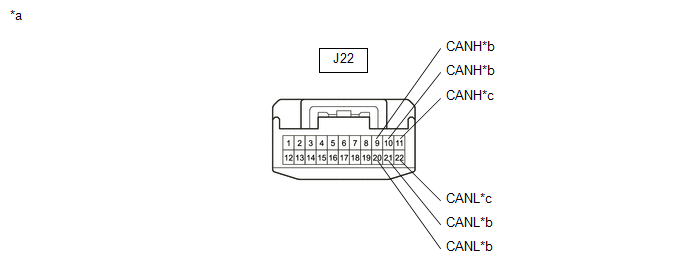 Text in Illustration
|
*a |
Front view of wire harness connector (to No. 6 CAN junction connector) |
*b |
to Central Gateway ECU (Network Gateway ECU) |
|
*c |
to Navigation Receiver Assembly (for Navigation Receiver Type) or Radio and Display Receiver Assembly (for Radio and Display Type) |
- |
- |
Standard Resistance:
|
Tester Connection |
Condition |
Specified Condition |
Connected to |
|---|---|---|---|
|
J22-9 (CANH) - J22-20 (CANL) |
Cable disconnected from negative (-) battery terminal |
108 to 132 Ω |
Central gateway ECU (network gateway ECU) |
|
J22-10 (CANH) - J22-21 (CANL) |
Cable disconnected from negative (-) battery terminal |
108 to 132 Ω |
Central gateway ECU (network gateway ECU) |
|
J22-11 (CANH) - J22-22 (CANL) |
Cable disconnected from negative (-) battery terminal |
200 Ω or higher |
Navigation receiver assembly*1 or Radio and display receiver assembly*2 |
- *1: for Navigation Receiver Type
- *2: for Radio and Display Type
|
Result |
Proceed to |
|---|---|
|
OK |
A |
|
NG (Central gateway ECU (network gateway ECU) CAN main line) |
B |
|
NG (ECU or sensor CAN branch lines) |
C |
| A | .gif) |
REPLACE NO. 6 CAN JUNCTION CONNECTOR |
| C | |
GO TO STEP 3 |
|
.gif)
|
2. |
CHECK FOR SHORT IN CAN BUS LINES (NO. 6 CAN JUNCTION CONNECTOR - CENTRAL GATEWAY ECU (NETWORK GATEWAY ECU)) |
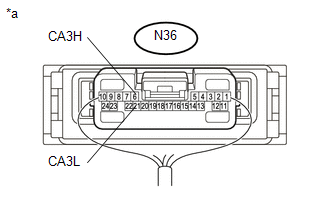
(a) Disconnect the N36 central gateway ECU (network gateway ECU) connector.
|
(b) Measure the resistance according to the value(s) in the table below. Standard Resistance:
|
|
.png)
| OK | |
REPLACE CENTRAL GATEWAY ECU (NETWORK GATEWAY ECU) |
| NG | |
REPAIR OR REPLACE CAN MAIN BUS LINES OR CONNECTOR (NO. 6 CAN JUNCTION CONNECTOR - CENTRAL GATEWAY ECU (NETWORK GATEWAY ECU)) |
|
3. |
CHECK FOR SHORT IN CAN BUS LINES (ECU, SENSOR) |
|
(a) Reconnect the CAN junction connector. |
|
(b) Disconnect the connector that includes terminals CANH and CANL from the ECU or sensor to which the short circuited CAN branch line is connected.
(c) Measure the resistance according to the value(s) in the table below.
Standard Resistance:
|
Tester Connection |
Condition |
Specified Condition |
|---|---|---|
|
N36-6 (CA3H) - N36-21 (CA3L) |
Cable disconnected from negative (-) battery terminal |
54 to 69 Ω |
|
*a |
Component with harness connected (Central Gateway ECU (Network Gateway ECU)) |
HINT:
If the resistance becomes normal (between 54 and 69 Ω) when the connector is disconnected from the ECU or sensor, there may be a short in the ECU or sensor.
| OK | |
REPLACE ECU OR SENSOR |
| NG | |
REPAIR OR REPLACE HARNESS OR CONNECTOR |
 Check Bus 3 Line for Short to +B
DESCRIPTION
There may be a short circuit between one of the CAN bus lines and +B when no
resistance exists between terminal 6 (CA3H) of the central gateway ECU (network
gateway ECU) and terminal ...
 Check Bus 3 Line for Short to GND
DESCRIPTION
There may be a short circuit between one of the CAN bus lines and GND when there
is no resistance between terminal 6 (CA3H) of the central gateway ECU (network gateway
ECU) and termin ...
Other materials:
Customize Parameters
CUSTOMIZE PARAMETERS
CUSTOMIZE LANE DEPARTURE ALERT SYSTEM
NOTICE:
When the customer requests a change in a function, first make sure that
the function can be customized.
Be sure to make a note of the current settings before customizing.
When troubleshooting a function, fir ...
Reassembly
REASSEMBLY
PROCEDURE
1. INSTALL UN-LOCK WARNING SWITCH ASSEMBLY (w/o Smart Key System)
(a) Engage the 2 claws to install the un-lock warning switch assembly to the
upper steering column bracket assembly.
2. INSTALL IGNITION SWITCH LOCK CYLINDER ASSEMBLY (w/o Smart Key System)
(a) T ...
Components
COMPONENTS
ILLUSTRATION
ILLUSTRATION
ILLUSTRATION
*1
CAMSHAFT
*2
CAMSHAFT BEARING CAP
*3
CAMSHAFT HOUSING SUB-ASSEMBLY RH
*4
CAMSHAFT TIMING GEAR BOLT (for Intake Side of Bank 1)
...
