Toyota Tacoma (2015-2018) Service Manual: AVC-LAN Circuit
DESCRIPTION
Each unit of the navigation system connected to the AVC-LAN (communication bus) transfers the switch signals using the AVC-LAN.
If a short to +B or short to ground occurs in the AVC-LAN, the navigation system will not function normally because communication is not possible.
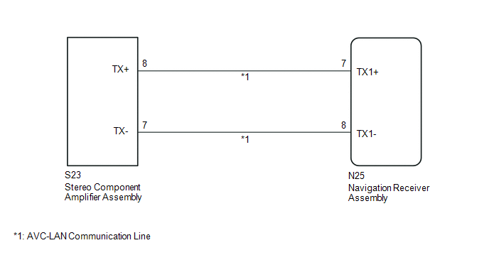
WIRING DIAGRAM
CAUTION / NOTICE / HINT
HINT:
The navigation receiver assembly is the master unit.
PROCEDURE
|
1. |
INSPECT NAVIGATION RECEIVER ASSEMBLY |
(a) Disconnect the navigation receiver assembly connectors.
|
(b) Measure the resistance according to the value(s) in the table below. Standard Resistance:
|
|
| NG | .gif) |
REPLACE NAVIGATION RECEIVER ASSEMBLY |
|
.gif)
|
2. |
CHECK HARNESS AND CONNECTOR (AVC-LAN CIRCUIT) |
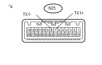
(a) Disconnect the N25 navigation receiver assembly connector.
(b) Disconnect the S23 stereo component amplifier assembly connector.
(c) Measure the resistance according to the value(s) in the table below.
Standard Resistance:
|
Tester Connection |
Condition |
Specified Condition |
|---|---|---|
|
N25-7 (TX1+) - S23-8 (TX+) |
Always |
Below 1 Ω |
|
N25-8 (TX1-) - S23-7 (TX-) |
Always |
Below 1 Ω |
|
N25-7 (TX1+) - Body ground |
Always |
10 kΩ or higher |
|
N25-8 (TX1-) - Body ground |
Always |
10 kΩ or higher |
| NG | |
REPAIR OR REPLACE HARNESS OR CONNECTOR |
|
|
3. |
INSPECT MALFUNCTIONING PARTS |
(a) Disconnect and reconnect each slave unit one by one until the master unit returns to normal operation.
HINT:
- Check all slave units.
- If disconnecting a slave unit causes the master unit to return to normal operation, the slave unit is defective and should be replaced.
OK:
Master unit returns to normal operation.
| OK | |
REPLACE MALFUNCTIONING PARTS |
| NG | |
REPLACE NAVIGATION RECEIVER ASSEMBLY |
 Mute Signal Circuit between Radio Receiver and Stereo Component Amplifier
DESCRIPTION
This circuit sends a signal to the stereo component amplifier assembly to mute
noise. Because of that, the noise produced by changing the sound source ceases.
If there is an open in th ...
 Vehicle Speed Signal Circuit between Stereo Component Amplifier and Combination
Meter
Vehicle Speed Signal Circuit between Stereo Component Amplifier and Combination
Meter
DESCRIPTION
The stereo component amplifier assembly receives a vehicle speed signal from
the combination meter assembly to control the ASL function.
HINT:
A voltage of 12 V or 5 V is outp ...
Other materials:
Four Wheel Drive (4WD) Range Signal Circuit Range / Performance (P279E)
DESCRIPTION
When the transfer position switch is switched, the 2-4 terminal and LO terminal
change to one of the following ON/OFF combinations listed in the table below.
Terminal
2WD
Between 2WD and H4
H4
Between H4 and L4
L4
...
Four-wheel drive system
Use the front-wheel drive control switch to select the following transfer modes.
H2 (high speed position, two-wheel
drive)
Use this for normal driving on dry hard-surfaced roads.
This position gives greater economy, quietest ride and least wear.
H4 (high speed position, four-wheel
drive) ...
Diagnostic Trouble Code Chart
DIAGNOSTIC TROUBLE CODE CHART
Dynamic Radar Cruise Control System
DTC No.
Detection Item
Link
C1A02
Vehicle Information Not Obtained
C1A0A
Front Radar Sensor Region Code Mismatch
...
