Toyota Tacoma (2015-2018) Service Manual: IG Signal Circuit
DESCRIPTION
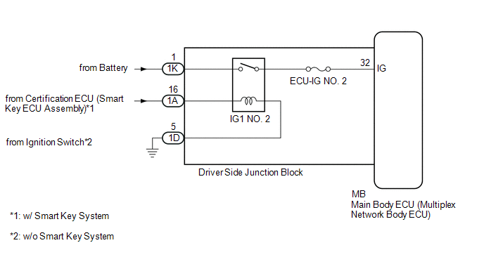
This circuit detects whether the ignition switch is ON or off, and sends this information to the main body ECU (multiplex network body ECU).
WIRING DIAGRAM
CAUTION / NOTICE / HINT
NOTICE:
- Inspect the fuses for circuits related to this system before performing the following inspection procedure.
- If the main body ECU (multiplex network body ECU) is replaced, refer
to Registration (See page
.gif) ).*1
).*1
- *1: w/ Smart Key System
PROCEDURE
|
1. |
READ VALUE USING TECHSTREAM (IG SW) |
(a) Connect the Techstream to the DLC3.
(b) Turn the ignition switch to ON.
(c) Turn the Techstream on.
(d) Enter the following menus: Body Electrical / Main Body / Data List.
(e) According to the display on the Techstream, read the Data List.
Main Body|
Tester Display |
Measurement Item/Range |
Normal Condition |
Diagnostic Note |
|---|---|---|---|
|
IG SW |
Ignition switch ON signal / ON or OFF |
ON: Ignition switch ON OFF: Ignition switch off |
"OFF" is also displayed for this item when the ignition switch is ACC. |
OK:
The display is as specified in the normal condition column.
| OK | .gif) |
PROCEED TO NEXT SUSPECTED AREA SHOWN IN PROBLEM SYMPTOMS TABLE |
|
.gif)
|
2. |
CHECK HARNESS AND CONNECTOR (DRIVER SIDE JUNCTION BLOCK - BATTERY AND BODY GROUND) |
|
(a) Disconnect the driver side junction block connectors. |
|
(b) Measure the voltage according to the value(s) in the table below.
Standard Voltage:
|
Tester Connection |
Condition |
Specified Condition |
|---|---|---|
|
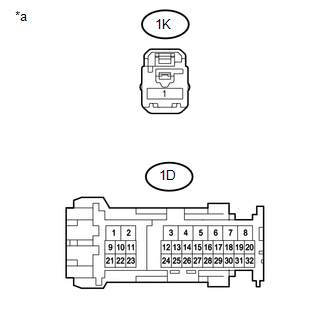
1K-1 - Body ground |
Always |
11 to 14 V |
(c) Measure the resistance according to the value(s) in the table below.
Standard Resistance:
|
Tester Connection |
Condition |
Specified Condition |
|---|---|---|
|
1D-5 - Body ground |
Always |
Below 1 Ω |
|
*a |
Front view of wire harness connector (to Driver Side Junction Block) |
| NG | |
REPAIR OR REPLACE HARNESS OR CONNECTOR |
|
|
3. |
CHECK HARNESS AND CONNECTOR (IG POWER SOURCE CIRCUIT) |
|
(a) Disconnect the driver side junction block connector. |
|
(b) Measure the voltage according to the value(s) in the table below.
Standard Voltage:
|
Tester Connection |
Switch Condition |
Specified Condition |
|---|---|---|
|
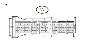
1A-16 - Body ground |
Ignition switch ON |
11 to 14 V |
|
*a |
Front view of wire harness connector (to Driver Side Junction Block) |
| NG | |
REPAIR OR REPLACE HARNESS OR CONNECTOR |
|
|
4. |
CHECK DRIVER SIDE JUNCTION BLOCK |
|
(a) Remove the driver side junction block (See page
|
|
(b) Reconnect the 1K, 1A and 1D driver side junction block connectors.
(c) Measure the voltage according to the value(s) in the table below.
Standard Voltage:
|
Tester Connection |
Switch Condition |
Specified Condition |
|---|---|---|
|
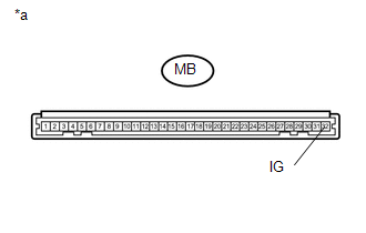
MB-32 (IG) - Body ground |
Ignition switch ON |
11 to 14 V |
|
*a |
Component without harness connected (Driver Side Junction Block) |
| OK | |
REPLACE MAIN BODY ECU (MULTIPLEX NETWORK BODY ECU) |
| NG | |
REPLACE DRIVER SIDE JUNCTION BLOCK |
 Automatic High Beam System does not Operate or Operation Indicator does not
Illuminate
Automatic High Beam System does not Operate or Operation Indicator does not
Illuminate
DESCRIPTION
The main body ECU (multiplex network body ECU) controls the automatic high beam
system based on signals received from the forward recognition camera.
WIRING DIAGRAM
CAUTION / NOTICE ...
 Turn Signal Switch Circuit
DESCRIPTION
The combination meter assembly receives the turn signal switch information and
controls the turn signal lights.
WIRING DIAGRAM
PROCEDURE
1.
READ VALUE USING ...
Other materials:
Stop Light Switch OFF Stuck Malfunction (C1426)
DESCRIPTION
The skid control ECU (brake actuator assembly) inputs the stop light signal and
brake operation condition. When the brake pedal is depressed and the stop light
switch signal is not input, C1426 is output.
DTC No.
Detection Item
DTC Detection Conditi ...
Replacement
REPLACEMENT
PROCEDURE
1. RECOVER REFRIGERANT FROM REFRIGERATION SYSTEM
(a) Start the engine.
(b) Operate the cooler compressor under the conditions shown below:
Item
Condition
Engine Speed
Idling
Operating Time
3 minu ...
How To Proceed With Troubleshooting
CAUTION / NOTICE / HINT
HINT:
The wireless door lock control system troubleshooting procedure is based
on the premise that the power door lock control system is operating normally.
Check the power door lock control system first before troubleshooting the
wireless door lock cont ...
