Toyota Tacoma (2015-2018) Service Manual: Air Outlet Damper Position Sensor Circuit (B1433/33)
DESCRIPTION
This sensor detects the position of the mode damper and sends the appropriate signals to the air conditioning amplifier assembly. The position sensor is built into the No. 1 air conditioning radiator damper servo sub-assembly (for mode switching).
|
DTC No. |
DTC Detection Condition |
Trouble Area |
|---|---|---|
|
B1433/33 |
Short to ground or power source circuit mode damper position sensor circuit. |
|
WIRING DIAGRAM
PROCEDURE
|
1. |
READ VALUE USING TECHSTREAM |
(a) Connect the Techstream to the DLC3.
(b) Turn the ignition switch to ON.
(c) Turn the Techstream on.
(d) Operate the mode switch.
(e) Enter the following menus: Body Electrical / Air Conditioner / Data List.
(f) Check the value(s) by referring to the table below.
Air Conditioner|
Tester Display |
Measurement Item/Range |
Normal Condition |
Diagnostic Note |
|---|---|---|---|
|
Air Outlet Damper Position |
Mode damper servo motor actual position / Min.: -14.0% Max.: 113.5% |
FACE: 0.0% DEF: 100.0% |
- |
|
Air Outlet Damper Target |
Mode damper servo motor target position / Min.: -14.0% Max.: 113.5% |
FACE: 0.0% DEF: 100.0% |
- |
OK:
The display is as specified in the Normal Condition column.
|
Result |
Proceed to |
|---|---|
|
NG |
A |
|
OK (When troubleshooting according to Problem Symptoms Table) |
B |
|
OK (When troubleshooting according to the DTC) |
C |
| B | .gif) |
PROCEED TO NEXT SUSPECTED AREA SHOWN IN PROBLEM SYMPTOMS TABLE |
| C | |
REPLACE AIR CONDITIONING AMPLIFIER ASSEMBLY |
|
.gif)
|
2. |
INSPECT NO. 1 AIR CONDITIONING RADIATOR DAMPER SERVO SUB-ASSEMBLY (FOR MODE SWITCHING) |
(a) Remove the No. 1 air conditioning radiator damper servo sub-assembly (for
mode switching) (See page .gif) ).
).
(b) Inspect the No. 1 air conditioning radiator damper servo sub-assembly (for
mode switching) (See page ).
| NG | |
REPLACE NO. 1 AIR CONDITIONING RADIATOR DAMPER SERVO SUB-ASSEMBLY (FOR MODE SWITCHING) |
|
|
3. |
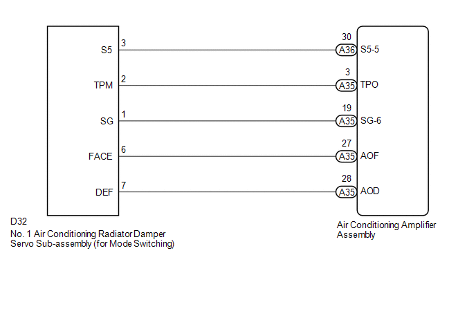
CHECK HARNESS AND CONNECTOR (NO. 1 AIR CONDITIONING RADIATOR DAMPER SERVO SUB-ASSEMBLY - AIR CONDITIONING AMPLIFIER ASSEMBLY) |
(a) Disconnect the D32 No. 1 air conditioning radiator damper servo sub-assembly (for mode switching) connector.
(b) Disconnect the A35 air conditioning amplifier assembly connector.
(c) Measure the resistance according to the value(s) in the table below.
Standard Resistance:
|
Tester Connection |
Condition |
Specified Condition |
|---|---|---|
|
D32-3 (S5) - A36-30 (S5-5) |
Always |
Below 1 Ω |
|
D32-2 (TPM) - A35-3 (TPO) |
Always |
Below 1 Ω |
|
D32-1 (SG) - A35-19 (SG-6) |
Always |
Below 1 Ω |
|
D32-3 (S5) or A36-30 (S5-5) - Body ground |
Always |
10 kΩ or higher |
|
D32-2 (TPM) or A35-3 (TPO) - Body ground |
Always |
10 kΩ or higher |
|
D32-1 (SG) or A35-19 (SG-6) - Body ground |
Always |
10 kΩ or higher |
| OK | |
REPLACE AIR CONDITIONING AMPLIFIER ASSEMBLY |
| NG | |
REPAIR OR REPLACE HARNESS OR CONNECTOR |
 Air Outlet Damper Control Servo Motor Circuit (B1443/43)
DESCRIPTION
This No. 1 air conditioning radiator damper servo sub-assembly (for mode switching)
is controlled by the air conditioning amplifier assembly and moves the mode damper
to the desired p ...
 Air Mix Damper Position Sensor Circuit (Driver Side) (B1436/36)
DESCRIPTION
This sensor detects the position of the air mix damper (for driver side) and
sends the appropriate signals to the air conditioning amplifier assembly. The position
sensor is built int ...
Other materials:
Installation
INSTALLATION
CAUTION / NOTICE / HINT
HINT:
Use the same procedure for both the LH and RH sides.
The procedure described below is for the LH side.
PROCEDURE
1. INSTALL FOG LIGHT ASSEMBLY
(a) Engage the 2 guides to install the fog light assembly.
(b) Install the screw.
(c) Co ...
Removal
REMOVAL
PROCEDURE
1. REMOVE STEERING PAD
(See page )
2. REMOVE STEERING WHEEL ASSEMBLY
3. REMOVE LOWER STEERING COLUMN COVER
4. REMOVE UPPER STEERING COLUMN COVER
5. REMOVE SPIRAL CABLE SUB-ASSEMBLY WITH SENSOR
(a) Slide the slider and disconnect the airbag connector ...
Lost Communication with Power Source Control (B278C)
DESCRIPTION
DTC No.
DTC Detection Condition
Trouble Area
B278C
An internal malfunction occurs in the certification ECU (smart key ECU
assembly)
Certification ECU (smart key ECU assembly)
CAUTI ...
