Toyota Tacoma (2015-2018) Service Manual: Components
COMPONENTS
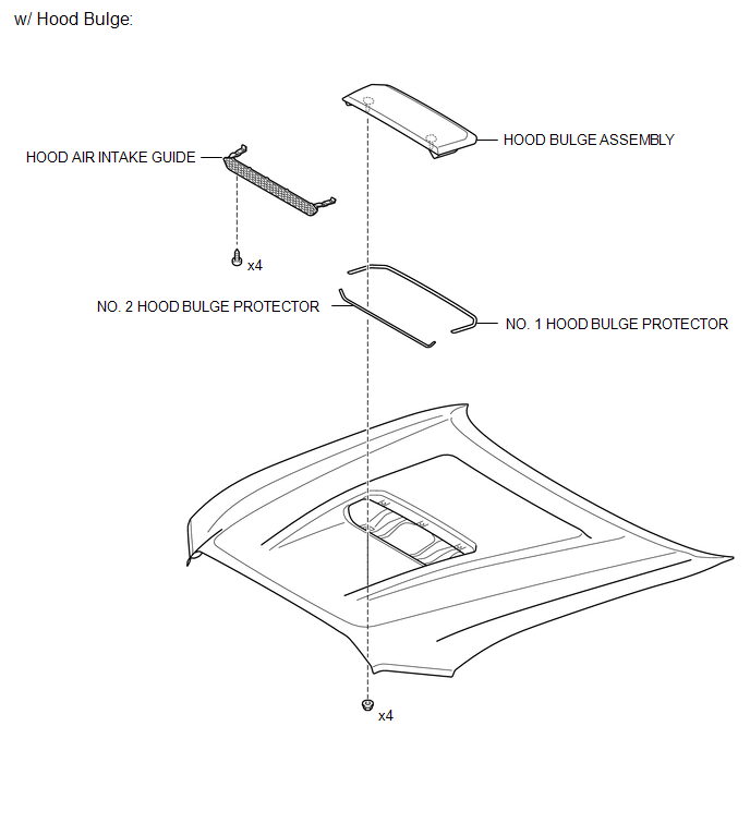
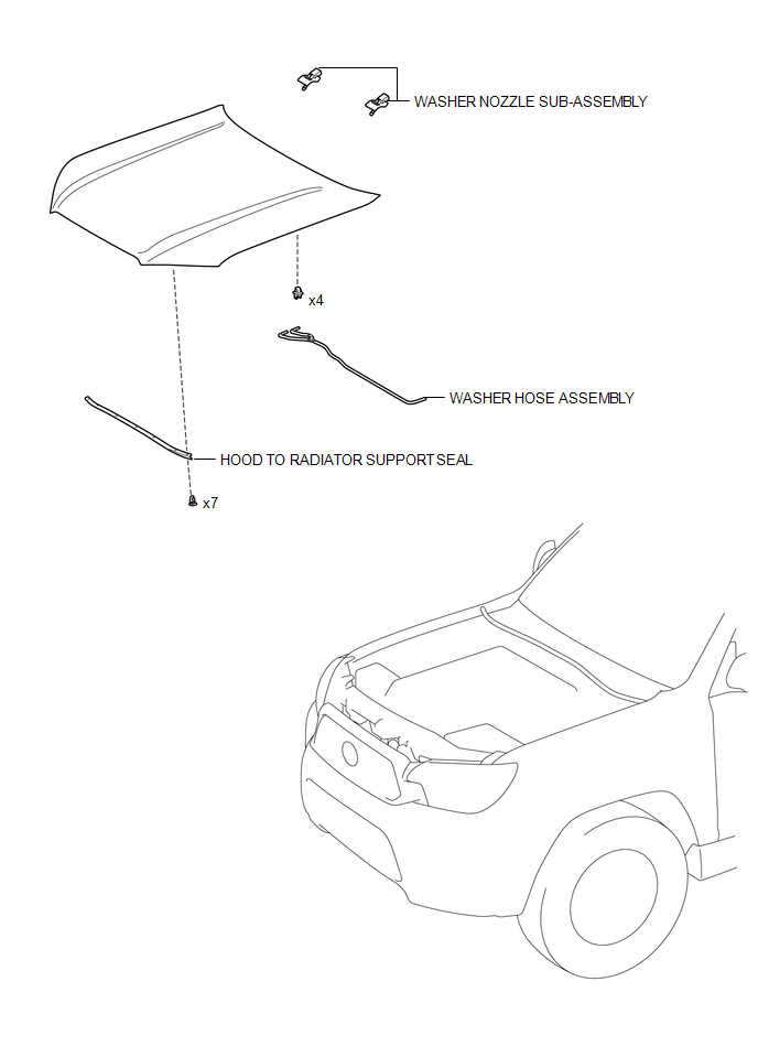
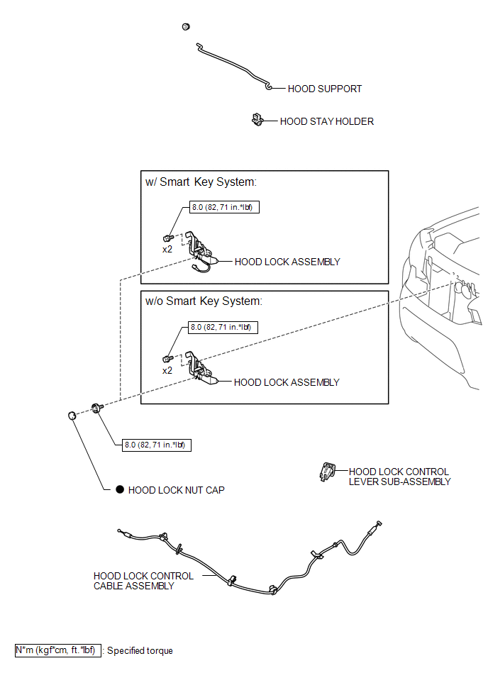
ILLUSTRATION
ILLUSTRATION
ILLUSTRATION
 Adjustment
ADJUSTMENT
CAUTION / NOTICE / HINT
HINT:
Centering bolts are used to mount the hood hinge and hood lock assembly.
The hood and hood lock assembly cannot be adjusted with the centering ...
 Disassembly
DISASSEMBLY
PROCEDURE
1. REMOVE HOOD BULGE ASSEMBLY (w/ Hood Bulge)
(a) Remove the 4 nuts.
(b) Disengage the clip from back side of the hood pa ...
Other materials:
Wireless remote control battery
Replace the battery with a new one if it is discharged.
■ You will need the following items:
Lithium battery CR2032
■ Replacing the battery
Remove the cover using a coin protected with tape etc.
Remove the discharged transmitter battery.
Insert a new battery with the “+” te ...
Before Starting Adjustment
BEFORE STARTING ADJUSTMENT
CAUTION / NOTICE / HINT
NOTICE:
When replacing the windshield glass of a vehicle equipped with a forward recognition
camera, make sure to use a Toyota genuine part. If a non-Toyota genuine part is
used, the forward recognition camera may not be able to be installed ...
Terminals Of Ecm
TERMINALS OF ECM
1. CHECK ECM
HINT:
The standard normal voltage between each pair of ECM terminals is shown in the
table below. The appropriate conditions for checking each pair of terminals are
also indicated. The result of checks should be compared with the standard normal
voltage for t ...
