Toyota Tacoma (2015-2018) Service Manual: On-vehicle Inspection
ON-VEHICLE INSPECTION
PROCEDURE
1. INSPECT FUEL CUT OPERATION
(a) Start the engine and warm it up.
(b) Increase the engine speed to at least 3500 rpm.
(c) Use a sound scope to check for fuel injector assembly operation noise.
(d) Check that when the accelerator pedal is released, fuel injector assembly operation noise stops momentarily, and then resumes.
If the result is not as specified, check the fuel injector assembly, wiring and ECM.
2. VISUALLY INSPECT HOSES, CONNECTIONS AND GASKETS
(a) Check that there are no cracks, leaks or damage.
NOTICE:
- Detachment or other problems with the engine oil level dipstick, oil filler cap sub-assembly, PCV hose and other components may cause the engine to run improperly.
- Air suction caused by disconnections, looseness or cracks in the parts of the air induction system between the throttle body with motor assembly and cylinder head sub-assembly, cylinder head LH will cause engine failure or engine malfunctions.
If the result is not as specified, replace parts as necessary.
3. INSPECT EVAPORATIVE EMISSION CONTROL SYSTEM
(a) Connect the Techstream to the DLC3.
(b) Remove the V-bank cover sub-assembly.
|
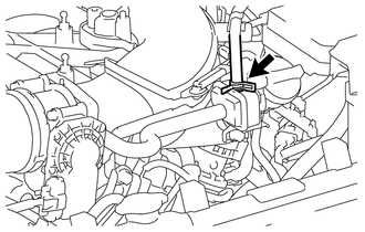
(c) Slide the hose clip and disconnect the purge line hose from the purge VSV. |
|
(d) Start the engine and turn the Techstream on.
(e) Enter the following menus: Powertrain / Engine / Active Test / Activate the VSV for EVAP Control.
OK:
|
Tester Operation |
Specified Condition |
|---|---|
|
EVAP VSV: OFF |
Purge VSV has no suction |
|
EVAP VSV: ON |
Purge VSV has suction |
(f) Connect the purge line hose to the purge VSV, and slide the hose clip to secure it.
(g) Install the V-bank cover sub-assembly.
4. INSPECT FUEL CUTOFF VALVE AND FILL CHECK VALVE
(a) Remove the fuel tank assembly.
Click here .gif)
|
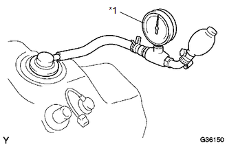
(b) Connect the pressure gauge to the vent hose port. Text in Illustration
|
|
(c) Install the fuel tank assembly with the fuel tank vent hose disconnected.
(d) Fill the fuel tank assembly with fuel.
(e) Apply pressure at 4 kPa (41 kgf/cm2, 0.58 psi) to the vent port of the fuel tank assembly.
HINT:
Check the amount of fuel left in the fuel tank assembly.
|
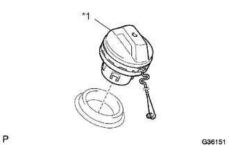
(f) Remove the fuel tank cap assembly, and check that the pressure decreases. If the pressure does not decrease, replace the fuel tank assembly. Text in Illustration
|
|
(g) Reconnect the fuel tank vent hose to the fuel tank assembly.
5. INSPECT AIR INLET LINE
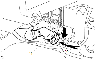
(a) Disconnect the fuel tank vent hose from the charcoal canister assembly.
.png)
.png) |
Push |
(1) Push the fuel tank vent hose deep inside.
(2) Pinch portion A to disconnect the fuel tank vent hose from the charcoal canister assembly as shown in the illustration.
NOTICE:
- Remove any dirt and foreign objects from the fuel tank vent hose connector before performing the work.
- Do not allow any scratches or foreign objects on the parts when disconnecting, as the fuel tank vent hose connector has the O-ring that seals the pipe.
- Perform the work by hand. Do not use any tools.
- Do not forcibly bend, twist or turn the nylon tube.
- Protect the disconnected part by covering it with a vinyl bag after disconnecting the fuel tank vent hose.
- If the fuel tank vent hose connector and pipe are stuck, push and pull them to release.
.png)
|
*1 |
Fuel Tank Vent Hose Retainer |
|
*2 |
Fuel Tank Vent Hose Connector |
|
*3 |
O-ring |
|
|
Pinch |
.png) |
Pull |
|
(b) Check that air flows freely into the fuel tank vent hose. If air cannot flow freely into the fuel tank vent hose, repair or replace the fuel tank vent hose. |
|
|
(c) Reconnect the fuel tank vent hose to the charcoal canister assembly. (1) Align the fuel tank vent hose connector with the charcoal canister assembly, then push in the fuel tank vent hose until the retainer makes a "click" sound to connect the fuel tank vent hose to the charcoal canister assembly. NOTICE:
|
|
.png)

 Parts Location
PARTS LOCATION
ILLUSTRATION
*1
FUEL TANK CAP ASSEMBLY
*2
CHARCOAL CANISTER ASSEMBLY
*3
CHARCOAL CANISTER LEAK DETECTION PUMP ...
Other materials:
Installation
INSTALLATION
PROCEDURE
1. INSTALL FRONT DIFFERENTIAL CARRIER ASSEMBLY
(a) Connect the actuator hose and connector.
(b) Install the No. 1 mounting support with the 3 bolts.
Torque:
186 N·m {1899 kgf·cm, 138 ft·lbf}
(c) Install the No. 2 mounting support with the 2 bolts.
Torque:
160 N ...
Navigation Receiver Assembly Communication Stop Mode
DESCRIPTION
Detection Item
Symptom
Trouble Area
Navigation Receiver Assembly Communication Stop Mode
Either condition is met:
Communication stop for "Display and Navigation (AVN1)" is indicated
on the "C ...
Inspection
INSPECTION
PROCEDURE
1. INSPECT FRONT SHOCK ABSORBER ASSEMBLY
(a) Compress and extend the shock absorber rod and check that there is no abnormal
resistance or unusual sound during operation.
If there is any abnormality, replace the front shock absorber with a new one.
NOTICE:
When disposin ...
