Toyota Tacoma (2015-2018) Service Manual: Vanity Light
Components
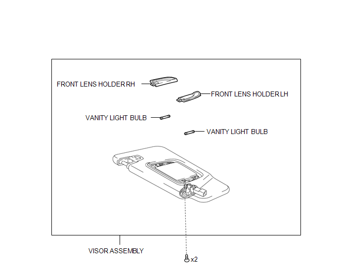
COMPONENTS
ILLUSTRATION
Removal
REMOVAL
CAUTION / NOTICE / HINT
HINT:
- Use the same procedures for the LH and RH side.
- The procedures listed below are for the LH side.
PROCEDURE
1. REMOVE VISOR ASSEMBLY
|
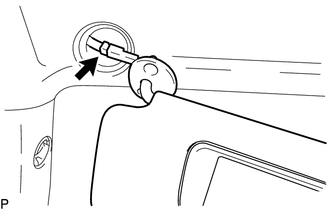
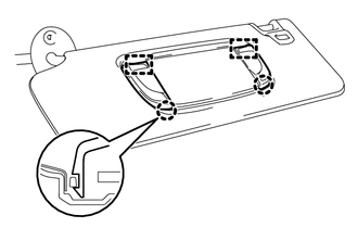
(a) Disengage the guide to separate the visor shaft. |
|
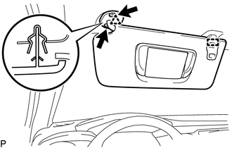
(b) Remove the 2 screws.
(c) Disengage the clip to separate the visor assembly.
|
(d) Disconnect the connector to remove the visor assembly. |
|
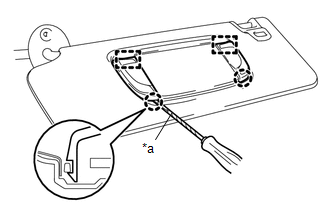
2. REMOVE VANITY LIGHT BULB
|
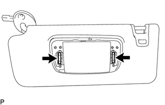
(a) Using a screwdriver with its tip wrapped in protective tape, disengage the 2 claws and 2 guides to remove the front lens holder LH and front lens holder RH. Text in Illustration
|
|
|
(b) Remove the 2 vanity light bulbs from the visor assembly. |
|
Installation
INSTALLATION
CAUTION / NOTICE / HINT
HINT:
- Use the same procedures for the LH and RH side.
- The procedures listed below are for the LH side.
PROCEDURE
1. INSTALL VANITY LIGHT BULB
(a) Install the 2 vanity light bulbs to the visor assembly.
|
(b) Engage the 2 guides and 2 claws to install the front lens holder LH and front lens holder RH. |
|
2. INSTALL VISOR ASSEMBLY
(a) Connect the connector.
(b) Engage the clip to install the visor assembly.
(c) Install the 2 screws.
(d) Engage the guide to install the visor shaft.
 Trailer Socket
Components
COMPONENTS
ILLUSTRATION
Removal
REMOVAL
PROCEDURE
1. REMOVE TRAILER SOCKET
(a) Disconnect the connector.
(b) Di ...

Other materials:
Installation
INSTALLATION
CAUTION / NOTICE / HINT
HINT:
Use the same procedure for both the RH and LH sides.
The procedure described below is for the LH side.
PROCEDURE
1. INSTALL CURTAIN SHIELD AIRBAG ASSEMBLY
(a) Insert the 5 hooks, install 6 new bolts, 2 new clips with pins and 2 new
...
Vehicle data recordings
Your Toyota is equipped with several sophisticated computers that will record
certain data, such as: • Engine speed
• Accelerator status
• Brake status
• Vehicle speed
• Shift position (except manual transmission)
The recorded data varies according to the vehicle grade level and opt ...
Registration
REGISTRATION
PROCEDURE
1. BEFORE REGISTRATION
NOTICE:
The transmitter ID is written on the tire pressure warning valve and transmitter.
It is not possible to read the transmitter ID after installing the tire onto the
wheel. Therefore, make a note of the transmitter ID before installing the t ...
