Toyota Tacoma (2015-2018) Service Manual: Trailer Socket
Components
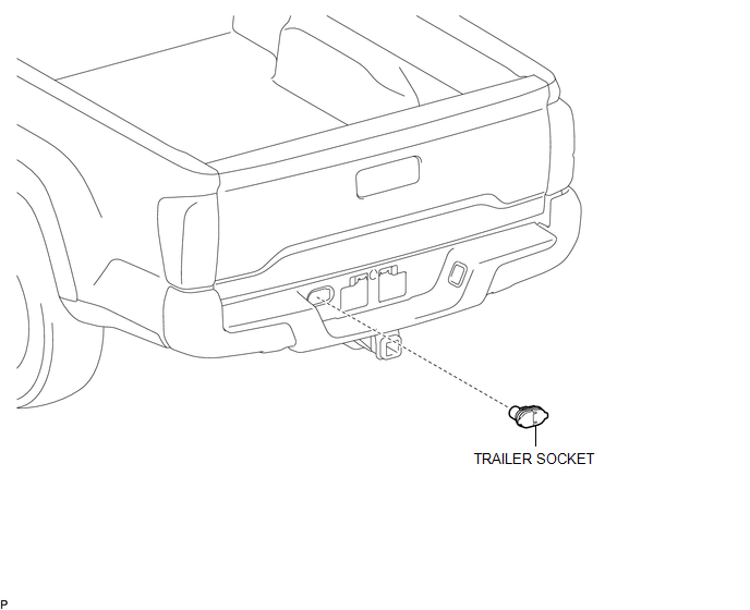
COMPONENTS
ILLUSTRATION
Removal
REMOVAL
PROCEDURE
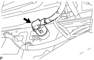
1. REMOVE TRAILER SOCKET
|
(a) Disconnect the connector. |
|
|
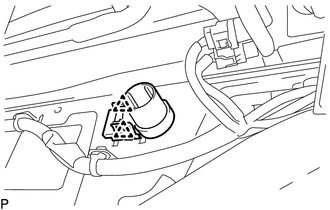
(b) Disengage the 2 clips to remove the trailer socket. |
|
Installation
INSTALLATION
PROCEDURE
1. INSTALL TRAILER SOCKET
(a) Engage the 2 clips to install the trailer socket.
(b) Connect the connector.
 Towing Tail Relay
Inspection
INSPECTION
PROCEDURE
1. INSPECT TOWING TAIL RELAY
(a) Check the resistance.
(1) Using an ohmmeter, measure the resistance between the terminals.
Standard:
Tester Conn ...
 Vanity Light
Components
COMPONENTS
ILLUSTRATION
Removal
REMOVAL
CAUTION / NOTICE / HINT
HINT:
Use the same procedures for the LH and RH side.
The procedures listed below are for the LH sid ...
Other materials:
Dtc Check / Clear
DTC CHECK / CLEAR
1. CHECK DTC
(a) Connect the Techstream to the DLC3.
(b) Turn the ignition switch to ON.
(c) Turn the blind spot monitor main switch assembly (warning canceling switch
assembly) on.
(d) Turn the Techstream on.
(e) Enter the following menus: Body Electrical / Blind Spot Moni ...
Definition Of Terms
DEFINITION OF TERMS
Term
Definition
Monitor Description
Description of what the ECM monitors and how it detects malfunctions
(monitoring purpose and details).
Related DTCs
A group of diagnostic trouble codes that are ...
Precaution
PRECAUTION
1. Check that the battery cables are connected to the correct terminals.
2. Disconnect the battery cables when the battery is given a quick charge.
3. Do not perform tests with a high voltage insulation resistance tester.
4. Never disconnect the battery while the engine is running.
5 ...
