Toyota Tacoma (2015-2018) Service Manual: USB Audio System Recognition/Play Error
DESCRIPTION
When a USB device or "iPod" is connected to the USB jack of the No. 1 stereo jack adapter assembly, it must have playable files. The device must also communicate with and be recognized by the navigation receiver assembly. This diagnosis procedure is for when a device is not recognized, or files from the device cannot be played normally.
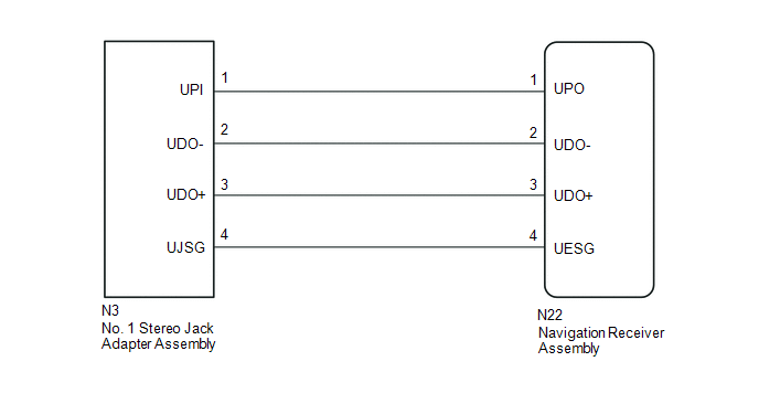
WIRING DIAGRAM
CAUTION / NOTICE / HINT
HINT:
- When a large amount of data is in a USB device, it may take a while to begin play.
- When using a USB device, files that are protected by copy protection cannot be played.
- When files are not played in the sorted order, perform the following
procedure before inspection.
- Add numbers in front of the file names.
- Put the files in a folder and copy the folder data to the USB device.
PROCEDURE
|
1. |
CHECK USB DEVICE OR "iPod" |
(a) Disconnect the USB device or "iPod" from the No. 1 stereo jack adapter assembly.
(b) Check if playable files are present on the USB device or "iPod".
HINT:
Refer to System Description for playable files (See page
.gif) ).
).
(c) Check if the USB device is a compatible format or "iPod" is a compatible version.
HINT:
Refer to System Description for compatible formats and versions (See page
).
|
Result |
Proceed to |
|---|---|
|
No playable files exist, or incompatible device format or version |
A |
|
Playable files exist, and compatible device format or version |
B |
| A | .gif) |
USB DEVICE FORMAT WAS INCOMPATIBLE, "iPod" VERSION WAS INCOMPATIBLE, OR NO PLAYABLE FILES PRESENT |
|
.gif)
|
2. |
CHECK HARNESS AND CONNECTOR (NAVIGATION RECEIVER ASSEMBLY - NO. 1 STEREO JACK ADAPTER ASSEMBLY) |
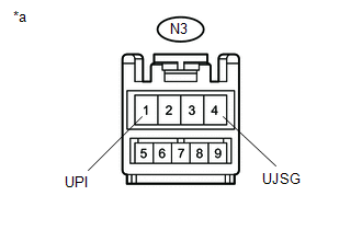
(a) Disconnect the N3 No. 1 stereo jack adapter assembly connector.
(b) Disconnect the N22 navigation receiver assembly connector.
(c) Measure the resistance according to the value(s) in the table below.
Standard Resistance:
|
Tester Connection |
Condition |
Specified Condition |
|---|---|---|
|
N3-1 (UPI) - N22-1 (UPO) |
Always |
Below 1 Ω |
|
N3-2 (UDO-) - N22-2 (UDO-) |
Always |
Below 1 Ω |
|
N3-3 (UDO+) - N22-3 (UDO+) |
Always |
Below 1 Ω |
|
N3-4 (UJSG) - N22-4 (UESG) |
Always |
Below 1 Ω |
|
N3-1 (UPI) - Body ground |
Always |
10 kΩ or higher |
|
N3-2 (UDO-) - Body ground |
Always |
10 kΩ or higher |
|
N3-3 (UDO+) - Body ground |
Always |
10 kΩ or higher |
|
N3-4 (UJSG) - Body ground |
Always |
10 kΩ or higher |
| NG | |
REPAIR OR REPLACE HARNESS OR CONNECTOR |
|
|
3. |
INSPECT NAVIGATION RECEIVER ASSEMBLY (NO. 1 STEREO JACK ADAPTER ASSEMBLY POWER SOURCE) |
(a) Reconnect the N22 navigation receiver assembly connector.
|
(b) Measure the voltage according to the value(s) in the table below. Standard Voltage:
|
|
| NG | |
REPLACE NAVIGATION RECEIVER ASSEMBLY |
|
|
4. |
FORMAT USB DEVICE OR RESTORE "iPod" AND RECHECK |
(a) Delete all files in the USB device or "iPod" and format/restore it.
(b) Save the data again and check if it can be played on the in-vehicle device.
NOTICE:
Formatting a USB device or restoring an "iPod" erases all music on the device. Ensure that backup music data is available before performing this operation.
OK:
Malfunction disappears.
| OK | |
END |
|
|
5. |
REPLACE USB DEVICE OR "iPod" |
(a) Turn the ignition switch off.
HINT:
When one of these DTCs has been stored, it is necessary to turn off the ignition switch to make it possible for the vehicle to recognize a new device when it is connected.
(b) Turn the ignition switch to ACC.
(c) Connect a known good USB device or "iPod" to the No. 1 stereo jack adapter assembly.
HINT:
- If the malfunction occurred when a USB device was in use, use another USB device for the inspection. If the malfunction occurred when an "iPod" was in use, use another "iPod" for the inspection.
- Refer to System Description for compatible formats and versions (See
page ).
|
|
6. |
CHECK USB DEVICE OR "iPod" |
(a) Check if a USB device or "iPod" is recognized by the navigation receiver assembly, and if information such as track, artist and album names are displayed on the screen.
OK:
Malfunction disappears.
| OK | |
USB DEVICE OR "iPod" WAS INCOMPATIBLE OR DEFECTIVE |
| NG | |
PROCEED TO NEXT SUSPECTED AREA SHOWN IN PROBLEM SYMPTOMS TABLE |
 Portable Player cannot be Registered
CAUTION / NOTICE / HINT
HINT:
Some versions of "Bluetooth" compatible audio players may not function, or the
function may be limited using the navigation receiver assembly, even if the p ...
 Black Screen
PROCEDURE
1.
CHECK DISPLAY SETTING
(a) Check that the display is not in "Screen Off" mode.
OK:
The display setting is not in "Screen Off" mode. ...
Other materials:
Clock
Adjusts the hours
Adjusts the minutes
■The clock is displayed when
The engine switch is in the ACC or ON position.
■When disconnecting and reconnecting battery terminals
The time display will automatically be set to 1:00. ...
Installation
INSTALLATION
PROCEDURE
1. INSTALL REAR ENGINE OIL SEAL
(a) Apply MP grease to the lip of a new rear engine oil seal.
NOTICE:
Keep the lip free of foreign matter.
(b) Using SST, tap in a new rear engine oil seal until its surface is
flush with the rear engine oil seal retainer ed ...
Dtc Check / Clear
DTC CHECK / CLEAR
CHECK DTC
(a) Connect the Techstream to the DLC3.
(b) Turn the ignition switch to ON.
(c) Turn the Techstream on.
(d) Enter the following menus: Chassis / LKA/LDA / Trouble Codes.
(e) Check for DTCs.
Click here
CLEAR DTC
(a) Connect the Techstream to the DLC3.
(b) Turn ...
