Toyota Tacoma (2015-2018) Service Manual: Transmitter Battery(w/ Smart Key System)
Replacement
REPLACEMENT
CAUTION / NOTICE / HINT
NOTICE:
Take extra care when handling these precision electronic components.
PROCEDURE
1. REMOVE TRANSMITTER BATTERY
|
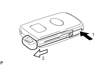
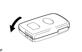
(a) Push the release hook knob and extract the mechanical key as shown in the illustration. Text in Illustration
|
|
|
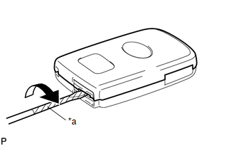
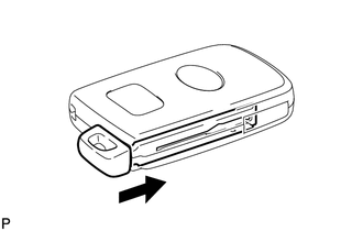
(b) Insert a precision screwdriver with its tip wrapped in protective tape into the gap, and turn the screwdriver to remove the transmitter housing cover. Text in Illustration
|
|
|
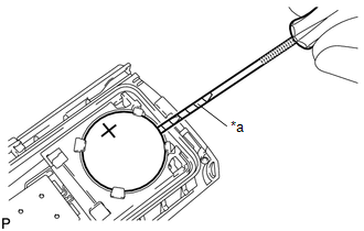
(c) Using a screwdriver with its tip wrapped in protective tape, remove the transmitter battery. Text in Illustration
NOTICE:
|
|
2. INSTALL TRANSMITTER BATTERY
|
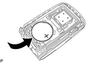
(a) Install a new transmitter battery with the positive (+) side facing upward, as shown in the illustration. NOTICE:
|
|
|
(b) Install the transmitter housing cover by pressing down on it as shown in the illustration. |
|
|
(c) Insert the mechanical key as shown in the illustration. |
|
(d) Press one of the transmitter switches and check that the LED illuminates.
OK:
Transmitter LED illuminates when switch is pressed.
 Entry Exterior Alarm and Answer-back Buzzer do not Sound
DESCRIPTION
The smart key system (for Entry Function) uses the wireless door lock buzzer
to perform various vehicle exterior warnings. When the conditions of each warning
are met, the certificati ...
 Unlock Warning Switch
Components
COMPONENTS
ILLUSTRATION
Inspection
INSPECTION
PROCEDURE
1. INSPECT UNLOCK WARNING SWITCH ASSEMBLY
(a) Check the resistance.
(1) Measure the resistance according to ...
Other materials:
On-vehicle Inspection
ON-VEHICLE INSPECTION
PROCEDURE
1. INSPECT DRIVER SEAT BELT WARNING LIGHT
HINT:
The seat belt warning light on the combination meter assembly is used for both
the driver seat and front passenger seat.
(a) Turn the ignition switch to ON.
(b) When the driver seat belt is not fastened, check th ...
Sound Quality is Bad Only when CD is Played (Volume is Too Low)
PROCEDURE
1.
REPLACE CD AND RECHECK
(a) Replace the CD with a known good one and check that the malfunction disappears.
OK:
Malfunction disappears.
OK
END
NG
REPLACE RADIO AND DISPLAY RECEIVER ASSEMBLY
...
Data List / Active Test
DATA LIST / ACTIVE TEST
1. DATA LIST
HINT:
Using the Techstream to read the Data List allows the values or states of switches,
sensors, actuators and other items to be read without removing any parts. This non-intrusive
inspection can be very useful because intermittent conditions or signals ...
