Toyota Tacoma (2015-2018) Service Manual: Transfer Shift Motor Control Circuit Low (P17A9)
DESCRIPTION
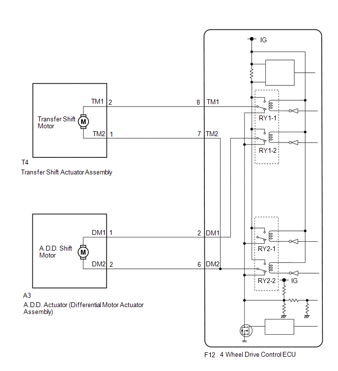
This DTC is output when a short to ground in the transfer shift motor and A.D.D. shift motor drive circuit is detected.
|
DTC No. |
Detection Item |
DTC Detection Condition |
Trouble Area |
|---|---|---|---|
|
P17A9 |
Transfer Shift Motor Control Circuit Low |
|
|
WIRING DIAGRAM
PROCEDURE
|
1. |
CHECK ACTUATOR ASSEMBLY (TRANSFER SHIFT MOTOR OR A.D.D. SHIFT MOTOR) |
(a) Disconnect the 4 wheel drive control ECU connector.
|
(b) Measure the resistance according to the value(s) in the table below. Standard Resistance: Transfer shift actuator assembly side:
|
|
|
Result |
Proceed to |
|---|---|
|
OK |
A |
|
NG (transfer shift actuator assembly side) |
B |
|
NG (A.D.D. actuator (differential vacuum actuator assembly) side) |
C |
| A | .gif) |
REPLACE 4 WHEEL DRIVE CONTROL ECU |
| C | |
GO TO STEP 3 |
|
.gif)
|
2. |
CHECK HARNESS AND CONNECTOR (4 WHEEL DRIVE CONTROL ECU AND TRANSFER SHIFT ACTUATOR ASSEMBLY - BODY GROUND) |
(a) Disconnect the F12 4 wheel drive control ECU connector.
(b) Disconnect the T4 transfer shift actuator assembly connector.
(c) Measure the resistance according to the value(s) in the table below.
Standard Resistance:
|
Tester Connection |
Condition |
Specified Condition |
|---|---|---|
|
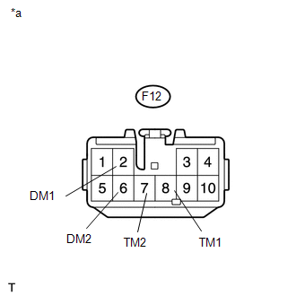
F12-8 (TM1) or T4-2 (TM1) - Body ground |
Always |
10 kΩ or higher |
|
F12-7 (TM2) or T4-1 (TM2) - Body ground |
Always |
10 kΩ or higher |
| OK | |
REPLACE TRANSFER SHIFT ACTUATOR ASSEMBLY |
| NG | |
REPAIR OR REPLACE HARNESS OR CONNECTOR |
|
3. |
CHECK HARNESS AND CONNECTOR (4 WHEEL DRIVE CONTROL ECU AND DIFFERENTIAL VACUUM ACTUATOR ASSEMBLY - BODY GROUND) |
(a) Disconnect the F12 4 wheel drive control ECU connector.
(b) Disconnect the A3 A.D.D. actuator (differential vacuum actuator assembly) connector.
(c) Measure the resistance according to the value(s) in the table below.
Standard Resistance:
|
Tester Connection |
Condition |
Specified Condition |
|---|---|---|
|
F12-2 (DM1) or A3-1 (DM1) - Body ground |
Always |
10 kΩ or higher |
|
F12-6 (DM2) or A3-2 (DM2) - Body ground |
Always |
10 kΩ or higher |
| OK | |
REPLACE DIFFERENTIAL VACUUM ACTUATOR ASSEMBLY |
| NG | |
REPAIR OR REPLACE HARNESS OR CONNECTOR |
 Four Wheel Drive (4WD) Range Signal Circuit Range / Performance (P279E)
DESCRIPTION
When the transfer position switch is switched, the 2-4 terminal and LO terminal
change to one of the following ON/OFF combinations listed in the table below.
Terminal
...
 Transfer Shift Motor Control Circuit High (P17AA)
DESCRIPTION
This DTC is output when a short to B+ in the transfer shift motor and A.D.D.
shift motor drive circuit is detected.
DTC No.
Detection Item
DTC Detectio ...
Other materials:
System Diagram
SYSTEM DIAGRAM
Communication Table
Sender
Receiver
Signal
Line
Millimeter Wave Radar Sensor Assembly
Forward Recognition Camera
Pre-collision alarm signal
Pre-collision braking operation signal
...
Vehicle Speed Sensor Circuit (C1AA3)
DESCRIPTION
The forward recognition camera receives vehicle speed signals from the skid control
ECU. If the skid control ECU receives a vehicle speed sensor malfunction signal,
it informs the forward recognition camera via CAN communication, and DTC C1AA3 is
stored.
DTC No.
...
Air Conditioning Compressor Magnetic Clutch Circuit
DESCRIPTION
When the air conditioning amplifier assembly is turned on, a magnetic clutch
on signal is sent from the MGC terminal of the air conditioning amplifier assembly.
Then, the MG CLT relay turns on to operate the magnetic clutch assembly.
WIRING DIAGRAM
CAUTION / NOTICE / HINT
NO ...
