Toyota Tacoma (2015-2018) Service Manual: Air Conditioning Compressor Magnetic Clutch Circuit
DESCRIPTION
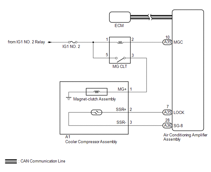
When the air conditioning amplifier assembly is turned on, a magnetic clutch on signal is sent from the MGC terminal of the air conditioning amplifier assembly. Then, the MG CLT relay turns on to operate the magnetic clutch assembly.
WIRING DIAGRAM
CAUTION / NOTICE / HINT
NOTICE:
- ECM malfunctions can affect the storage of this DTC. Therefore, check
all SFI system DTCs and confirm that the system is normal before performing
the following inspection (See page
.gif) ).
).
- Inspect the fuses for circuits related to this system before performing the following procedure.
PROCEDURE
|
1. |
CHECK FOR DTC (CAN COMMUNICATION SYSTEM) |
(a) Use the Techstream to check if the CAN communication system is functioning normally.
Result|
Result |
Proceed to |
|---|---|
|
CAN DTC is not output |
A |
|
CAN DTC is output |
B |
| B | .gif) |
GO TO CAN COMMUNICATION SYSTEM |
|
.gif)
|
2. |
INSPECT MG CLT RELAY |
(a) Remove the MG CLT relay.
(b) Inspect the MG CLT relay (See page ).
| NG | |
REPLACE MG CLT RELAY |
|
|
3. |
CHECK HARNESS AND CONNECTOR (MG CLT RELAY - POWER SOURCE CIRCUIT) |
(a) Remove the MG CLT relay.
(b) Measure the voltage according to the value(s) in the table below.
Standard Voltage:
|
Tester Connection |
Switch Condition |
Specified Condition |
|---|---|---|
|
MG CLT-1 - Body ground |
Ignition switch ON |
11 to 14 V |
|
MG CLT-5 - Body ground |
Ignition switch ON |
11 to 14 V |
| NG | |
REPAIR OR REPLACE HARNESS OR CONNECTOR |
|
|
4. |
CHECK HARNESS AND CONNECTOR (MG CLT RELAY - AIR CONDITIONING AMPLIFIER ASSEMBLY AND MAGNET-CLUTCH ASSEMBLY) |
(a) Remove the MG CLT relay.
(b) Disconnect the A35 air conditioning amplifier assembly connector.
(c) Disconnect the A1 magnet-clutch assembly connector.
(d) Measure the resistance according to the value(s) in the table below.
Standard Resistance:
|
Tester Connection |
Condition |
Specified Condition |
|---|---|---|
|
MG CLT-2 - A35-10 (MGC) |
Always |
Below 1 Ω |
|
MG CLT-3 - A1-1 (MG+) |
Always |
Below 1 Ω |
|
MG CLT-2 or A35-10 (MGC) - Body ground |
Always |
10 kΩ or higher |
|
MG CLT-3 or A1-1 (MG+) - Body ground |
Always |
10 kΩ or higher |
| NG | |
REPAIR OR REPLACE HARNESS OR CONNECTOR |
|
|
5. |
INSPECT MAGNET-CLUTCH ASSEMBLY |
(a) Remove the magnet-clutch assembly (See page
).
(b) Inspect the magnet-clutch assembly (See page
).
| NG | |
REPLACE MAGNET-CLUTCH ASSEMBLY |
|
|
6. |
INSPECT AIR CONDITIONING AMPLIFIER ASSEMBLY |
(a) Reconnect the A35 air conditioning amplifier assembly connector.
(b) Reconnect the A1 magnet-clutch assembly connector.
(c) Reinstall the MG CLT relay.
|
(d) Measure the voltage according to the value(s) in the table below. Standard Voltage:
|
|
| OK | |
PROCEED TO NEXT SUSPECTED AREA SHOWN IN PROBLEM SYMPTOMS TABLE |
| NG | |
REPLACE AIR CONDITIONING AMPLIFIER ASSEMBLY |
 Compressor Lock Sensor Circuit (B1422/22)
SYSTEM DESCRIPTION
The ECM sends the engine speed signal to the air conditioning amplifier assembly
via CAN communication.
The air conditioning amplifier assembly reads the difference between comp ...
 Pressure Sensor Circuit (B1423/23)
DESCRIPTION
This DTC is stored if refrigerant pressure on the high pressure side is extremely
low (176 kPa (1.8 kgf/cm2, 26 psi) or less) or extremely high (3140 kPa (32.0 kgf/cm2,
455 psi) or mo ...
Other materials:
Front Camera Module Communication Stop Mode
DESCRIPTION
Detection Item
Symptom
Trouble Area
Front Camera Module Communication Stop Mode
Either Condition is met:
Communication stop for "Front Camera Module" is indicated on
the "Communication Bus Ch ...
Driver Side Seat Belt Warning Light does not Operate
DESCRIPTION
When the ignition switch is ON, the airbag sensor assembly transmits front seat
inner belt status signals to the combination meter assembly through CAN. If the
driver seat belt is not fastened, the combination meter assembly blinks the driver
side seat belt warning light. If the s ...
Differential System(w/o Differential Lock)
Precaution
PRECAUTION
1. Before disassembly, clean the outside of the front and rear differential assembly
and remove any sand and mud to prevent it from entering the assembly during disassembly
and installation.
2. When removing connected parts made of a light alloy, such as front and rear ...
