Toyota Tacoma (2015-2018) Service Manual: Transfer Shift Motor Control Circuit Circuit Open (P17A8)
DESCRIPTION
This DTC is output when an open circuit in the transfer shift motor drive circuit is detected.
|
DTC No. |
Detection Item |
DTC Detection Condition |
Trouble Area |
|---|---|---|---|
|
P17A8 |
Transfer Shift Motor Control Circuit Circuit Open |
|
|
WIRING DIAGRAM
Refer to DTC P17A9 (See page .gif) ).
).
PROCEDURE
|
1. |
CHECK HARNESS AND CONNECTOR (4 WHEEL DRIVE CONTROL ECU - TRANSFER SHIFT ACTUATOR ASSEMBLY) |
(a) Disconnect the F12 4 wheel drive control ECU connector.
(b) Disconnect the T4 transfer shift actuator assembly connector.
(c) Measure the resistance according to the value(s) in the table below.
Standard Resistance:
|
Tester Connection |
Condition |
Specified Condition |
|---|---|---|
|
F12-8 (TM1) - T4-2 (TM1) |
Always |
Below 1 Ω |
|
F12-7 (TM2) - T4-1 (TM2) |
Always |
Below 1 Ω |
| NG | .gif) |
REPAIR OR REPLACE HARNESS OR CONNECTOR |
|
.gif)
|
2. |
INSPECT TRANSFER SHIFT ACTUATOR ASSEMBLY (TRANSFER SHIFT MOTOR) |
|
(a) Disconnect the T4 transfer shift actuator assembly connector. |
|
(b) Measure the resistance according to the value(s) in the table below.
Standard Resistance:
|
Tester Connection |
Condition |
Specified Condition |
|---|---|---|
|
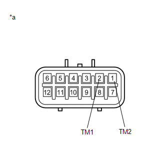
2 (TM1) - 1 (TM2) |
Always |
1.5 to 10 Ω |
|
*a |
Component without harness connected (Transfer Shift Actuator Assembly) |
| OK | |
REPLACE 4 WHEEL DRIVE CONTROL ECU |
| NG | |
REPLACE TRANSFER SHIFT ACTUATOR ASSEMBLY |
 Automatic Disconnecting Differential Motor Limit Switch Circuit (P17A4)
DESCRIPTION
When the A.D.D. actuator switches between 2WD and 4WD, the DL1 and DL2 terminals
of the limit switch and ADD terminal of the A.D.D. position switch change to one
of the following ON/O ...
 Four Wheel Drive (4WD) Range Signal Circuit Range / Performance (P279E)
DESCRIPTION
When the transfer position switch is switched, the 2-4 terminal and LO terminal
change to one of the following ON/OFF combinations listed in the table below.
Terminal
...
Other materials:
Removal
REMOVAL
CAUTION / NOTICE / HINT
HINT:
When removing the name plates or stripe tapes, heat the vehicle body or tail
gate and name plates or stripe tapes using a heat light.
Heating Temperature
Item
Temperature
Vehicle Body or Tail Gate
40 to 60 ...
VSC OFF Switch Circuit
DESCRIPTION
The skid control ECU assembly is connected to the combination meter assembly
via CAN communication.
Pressing the VSC OFF switch turns off TRAC operation, and pressing and holding
this switch turns off TRAC and VSC operation.
If TRAC and VSC operations are turned off, the TRAC OFF ...
Outer Mirror Switch
Inspection
INSPECTION
PROCEDURE
1. INSPECT OUTER MIRROR SWITCH ASSEMBLY
(a) Check the mirror select switch and mirror surface adjust switch.
(1) Turn the mirror select switch to the L position.
Text in Illustration
*a
Mirror Select and Surfac ...
