Toyota Tacoma (2015-2018) Service Manual: Daytime Running Light Relay Circuit
DESCRIPTION
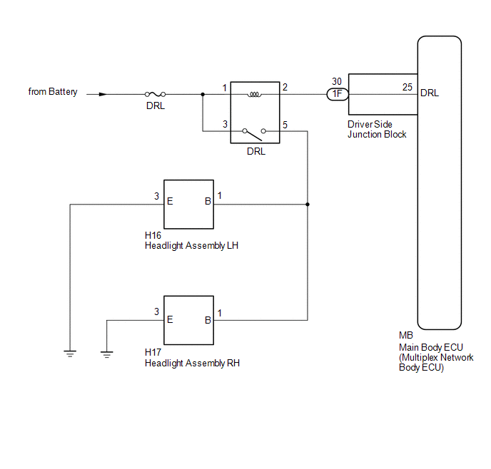
The main body ECU (multiplex network body ECU) controls the daytime running lights.
WIRING DIAGRAM
CAUTION / NOTICE / HINT
NOTICE:
- Inspect the fuses for circuits related to this system before performing the following inspection procedure.
- If the main body ECU (multiplex network body ECU) is replaced, refer
to Registration (See page
.gif) ).*1
).*1
- *1: w/ Smart Key System
PROCEDURE
|
1. |
PERFORM ACTIVE TEST USING TECHSTREAM (DAYTIME RUNNING LIGHT) |
(a) Connect the Techstream to the DLC3.
(b) Turn the ignition switch to ON.
(c) Turn the Techstream on.
(d) Enter the following menus: Body Electrical / Main Body / Active Test.
(e) Perform the Active Test according to the display on the Techstream.
Main Body|
Tester Display |
Test Part |
Control Range |
Diagnostic Note |
|---|---|---|---|
|
Daytime Running Light |
Daytime running lights |
ON/OFF |
- |
OK:
Daytime running lights illuminate.
| OK | .gif) |
PROCEED TO NEXT SUSPECTED AREA SHOWN IN PROBLEM SYMPTOMS TABLE |
|
.gif)
|
2. |
INSPECT RUNNING LIGHT RELAY (DRL) |
|
(a) Remove the running light relay. |
|
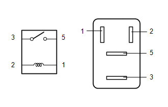
(b) Measure the resistance according to the value(s) in the table below.
Standard Resistance:
|
Tester Connection |
Condition |
Specified Condition |
|---|---|---|
|
3 - 5 |
Battery voltage not applied to terminals 1 and 2 |
10 kΩ or higher |
|
3 - 5 |
Battery voltage applied to terminals 1 and 2 |
Below 1 Ω |
| NG | |
REPLACE RUNNING LIGHT RELAY |
|
|
3. |
CHECK HARNESS AND CONNECTOR (BATTERY - RUNNING LIGHT RELAY) |
(a) Measure the voltage according to the value(s) in the table below.
Standard Voltage:
|
Tester Connection |
Condition |
Specified Condition |
|---|---|---|
|
Relay terminal 1 - Body ground |
Always |
11 to 14 V |
|
Relay terminal 3 - Body ground |
Always |
11 to 14 V |
| NG | |
REPAIR OR REPLACE HARNESS OR CONNECTOR |
|
|
4. |
CHECK HARNESS AND CONNECTOR (RUNNING LIGHT RELAY - DRIVER SIDE JUNCTION BLOCK AND BODY GROUND) |
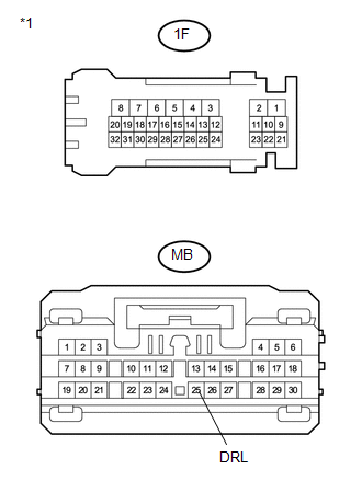
(a) Disconnect the 1F driver side junction block connector.
(b) Measure the resistance according to the value(s) in the table below.
Standard Resistance:
|
Tester Connection |
Condition |
Specified Condition |
|---|---|---|
|
Running light relay terminal 2 - 1F-30 |
Always |
Below 1 Ω |
|
1F-30 - Body ground |
Always |
10 kΩ or higher |
| NG | |
REPAIR OR REPLACE HARNESS OR CONNECTOR |
|
|
5. |
INSPECT DRIVER SIDE JUNCTION BLOCK |
|
(a) Remove the driver side junction block. |
|
(b) Measure the resistance according to the value(s) in the table below.
Standard Resistance:
|
Tester Connection |
Condition |
Specified Condition |
|---|---|---|
|
1F-30 - MB-25 (DRL) |
Always |
Below 1 Ω |
|
1F-30 - Body ground |
Always |
10 kΩ or higher |
|
*1 |
Component without harness connected (Driver Side Junction Block) |
| OK | |
PROCEED TO NEXT SUSPECTED AREA SHOWN IN PROBLEM SYMPTOMS TABLE |
| NG | |
REPLACE DRIVER SIDE JUNCTION BLOCK |
 ACC Signal Circuit
DESCRIPTION
This circuit detects whether the ignition switch is ACC or off, and sends this
information to the main body ECU (multiplex network body ECU).
WIRING DIAGRAM
CAUTION / NOTICE / HINT
...
 Headlight Dimmer Switch Circuit
DESCRIPTION
The main body ECU (multiplex network body ECU) receives the following switch
information:
Light control switch position is off (DRL OFF), tail, head or AUTO (DRL).
Dimmer ...
Other materials:
Abnormal Change in Output Signal of Rear Speed Sensor RH (Test Mode DTC) (C1277,...,C1416)
DESCRIPTION
Refer to DTCs C1401 and C1402 (See page ).
DTC Code
DTC Detection Condition
Trouble Area
C1277
C1278
Stored only during test mode.
Rear speed sensor RH/LH
Rear speed sensor rotor RH/LH (Rear ax ...
Low Power Supply Voltage Malfunction (C1241)
DESCRIPTION
If a malfunction is detected in the power supply circuit, the skid control ECU
(brake actuator assembly) stores this DTC and the fail-safe function prohibits ABS
operation.
This DTC is stored when the +BS terminal voltage deviates from the DTC detection
condition due to a malfunc ...
Microphone Circuit between Microphone and Radio Receiver
DESCRIPTION
The radio and display receiver assembly and telephone microphone assembly are
connected to each other using the microphone connection detection signal lines.
Using this circuit, the radio and display receiver assembly sends power to the
telephone microphone assembly, and the teleph ...
