Toyota Tacoma (2015-2018) Service Manual: Fog Light Relay
Inspection
INSPECTION
PROCEDURE
1. INSPECT FOG LIGHT RELAY
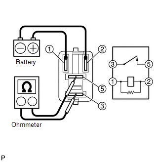
(a) Check the resistance.
(1) Using an ohmmeter, measure the resistance between the terminals.
Standard:
|
Tester Connection |
Specified Condition |
|---|---|
|
3-5 |
10 kΩ or higher |
|
3-5 |
Below 1 Ω (When battery voltage applied to terminals 1 and 2) |
If the result is not as specified, replace the fog light relay.
 Installation
INSTALLATION
CAUTION / NOTICE / HINT
HINT:
Use the same procedure for both the LH and RH sides.
The procedure described below is for the LH side.
PROCEDURE
1. INSTALL FOG LAMP A ...
 Front Door Courtesy Switch
Inspection
INSPECTION
PROCEDURE
1. INSPECT FRONT DOOR COURTESY SWITCH
(a) Check the resistance.
(1) Measure the resistance using an ohmmeter, and check the results in accordance
with the valu ...
Other materials:
Inspection
INSPECTION
PROCEDURE
1. INSPECT BRAKE DRUM INSIDE DIAMETER
(a) Using a brake drum gauge or equivalent, measure the inside diameter of the
drum.
Standard inside diameter:
254 mm (10.00 in.)
Maximum inside diameter:
256 mm (10.08 in.)
If the inside diameter is greater than the maximum, r ...
Additional Key cannot be Registered
DESCRIPTION
If additional registration is not possible, a malfunction in the certification
ECU (smart key ECU assembly), engine switch, electrical key transmitter sub-assembly
or steering lock ECU (steering lock actuator or UPR bracket assembly) is suspected.
CAUTION / NOTICE / HINT
NOTICE ...
Removal
REMOVAL
PROCEDURE
1. REMOVE ROOF HEADLINING ASSEMBLY (for LED Type Stop Light)
for Double Cab:
(See page
)
for Access Cab:
(See page
)
2. REMOVE CENTER STOP LIGHT ASSEMBLY (for Bulb Type Stop Light)
(a) Apply protective tape around the center stop light as ...
