Toyota Tacoma (2015-2018) Service Manual: Torque Converter And Drive Plate
Inspection
INSPECTION
PROCEDURE
1. INSPECT TORQUE CONVERTER ASSEMBLY
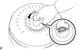
(a) Inspect the one-way clutch.
(1) Press on the spline of the stator with a finger and rotate the spline. Check that the spline rotates smoothly when turned clockwise and rotates with difficulty when turned counterclockwise.
 Text in Illustration
.png) |
Difficult |
.png) |
Smooth |
If necessary, clean the torque converter assembly and recheck the one-way clutch. Replace the torque converter assembly if the one-way clutch still fails the inspection.
|
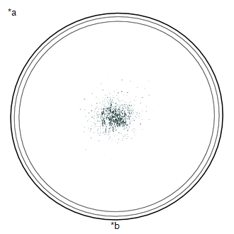
(b) Inspect the torque converter assembly. If any of the following problems are present, replace the torque converter assembly. Text in Illustration
HINT: The sample shows approximately 0.025 liters (0.026 US qts, 0.022 Imp. qts) of ATF in Petri dish, which has been taken from a torque converter assembly. |
|
(c) Replace the ATF in the torque converter assembly.
(1) If the ATF is discolored or has a foul odor, stir the ATF in the torque converter assembly and drain it before replacing the ATF.
|
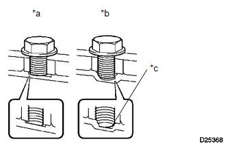
(d) Prevent deformation of the torque converter and damage to the oil pump gear. Text in Illustration
NOTICE: Make sure that all of the bolts are the same length and that the specified bolts are used. HINT: If there is any damage to the tip of a bolt for the torque converter assembly or to the bottom of a bolt hole, replace the bolt and torque converter assembly. |
|
2. INSPECT DRIVE PLATE AND RING GEAR SUB-ASSEMBLY
(a) Check the drive plate for damage.
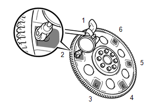 Text in Illustration
 |
Measurement Point |
(b) Set up a dial indicator and measure the runout at the 6 areas on the drive plate surface that contact the torque converter assembly.
Maximum runout:
0.30 mm (0.0118 in.)
If the runout is more than the maximum or the drive plate is damaged, replace the drive plate.
for 2GR-FKS: (See page .gif) )
)
for 2TR-FE: (See page
)
 Speed Sensor
Components
COMPONENTS
ILLUSTRATION
Removal
REMOVAL
PROCEDURE
1. REMOVE TRANSMISSION REVOLUTION SENSOR (NT)
(a) Disconnect the transmission revolution sensor (NT) connector.
...

Other materials:
FCM Destination Information Unmatched (C1AA1)
DESCRIPTION
When the forward recognition camera is replaced with a new one, the new forward
recognition camera attempts to store country specification information received
from the main body ECU (multiplex network body ECU) and ECM. If the country specification
information stored in the forwa ...
System Description
SYSTEM DESCRIPTION
1. LIN COMMUNICATION SYSTEM DESCRIPTION
The LIN communication system is used for communication between the components
in the tables below. If communication cannot be performed through LIN communication
because of an open in the communication lines or other reasons, the maste ...
If the vehicle becomes stuck
Carry out the following procedures if the tires spin or the vehicle becomes
stuck in mud, dirt, or snow.
Stop the engine. Set the parking
brake and put the shift lever in P (vehicles with an automatic transmission) or
N (vehicles with a manual transmission).
Remove the mud, snow, or sand f ...
