Toyota Tacoma (2015-2018) Service Manual: Tire Pressure Monitor ECU Communication Stop (C2179/79)
DESCRIPTION
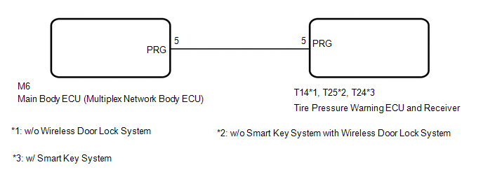
The main body ECU (multiplex network body ECU) sends signals to the tire pressure warning ECU and receiver via a direct line.
|
DTC No. |
Detection Item |
DTC Detection Condition |
Trouble Area |
Note |
|---|---|---|---|---|
|
C2179/79 |
Tire Pressure Monitor ECU Communication Stop |
Communication between the main body ECU (multiplex network body ECU) and tire pressure warning ECU and receiver is interrupted for 10 seconds or more. |
|
- |
WIRING DIAGRAM
CAUTION / NOTICE / HINT
NOTICE:
- When replacing the tire pressure warning ECU and receiver, read the transmitter IDs stored in the old ECU using the Techstream and write them down before removal.
- It is necessary to perform initialization (See page
.gif) ) after registration (See page
) of the transmitter IDs into the tire
pressure warning ECU and receiver after the ECU has been replaced.
) after registration (See page
) of the transmitter IDs into the tire
pressure warning ECU and receiver after the ECU has been replaced. - If the main body ECU (multiplex network body ECU) is replaced, refer
to Registration (See page ).*
*: w/ Smart Key System
PROCEDURE
|
1. |
CHECK HARNESS AND CONNECTOR (TIRE PRESSURE WARNING ECUAND RECEIVER - MAIN BODY ECU (MULTIPLEX NETWORK BODY ECU)) |
(a) Disconnect the T14*1, T25*2, T24*3 tire pressure warning ECU and receiver connector.
(b) Disconnect the M6 main body ECU (multiplex network body ECU) connector.
(c) Measure the resistance according to the value(s) in the table below.
Standard Resistance:
|
Tester Connection |
Condition |
Specified Condition |
|---|---|---|
|
T14-5 (PRG) - M6-5 (PRG)*1 T25-5 (PRG) - M6-5 (PRG)*2 T24-5 (PRG) - M6-5 (PRG)*3 |
Always |
Below 1 Ω |
|
T14-5 (PRG) or M6-5 (PRG) - Body ground*1 T25-5 (PRG) or M6-5 (PRG) - Body ground*2 T24-5 (PRG) or M6-5 (PRG) - Body ground*3 |
Always |
10 kΩ or higher |
- *1: w/o Wireless Door Lock System
- *2: w/o Smart Key System with Wireless Door Lock System
- *3: w/ Smart Key System
| NG | .gif) |
REPAIR OR REPLACE HARNESS OR CONNECTOR |
|
.gif)
|
2. |
REPLACE TIRE PRESSURE WARNING ECU AND RECEIVER |
(a) Replace the tire pressure warning ECU and receiver (See page
).
|
|
3. |
CHECK DTC OUTPUT |
(a) Clear the DTCs (See page ).
(b) Turn the ignition switch off.
(c) Turn the ignition switch to ON.
(d) Check for DTCs (See page ).
OK:
DTC C2179/79 is not output.
| OK | |
END |
| NG | |
REPLACE MAIN BODY ECU (MULTIPLEX NETWORK BODY ECU) |
 Initialization not Completed (C2177/77)
DESCRIPTION
Initialization is necessary if one of the following occurs:
The tire pressure warning ECU and receiver is replaced.
A tire pressure warning valve and transmitter is replaced. ...
 Initialization Switch (for Test Mode DTC) (C2198/98)
DESCRIPTION
During test mode, when the tire pressure warning reset switch is on, the tire
pressure warning light comes on and when the tire pressure warning reset switch
is off, the tire pressure ...
Other materials:
Manual transmission
■ Shifting the shift lever
6-speed models
Fully depress the clutch pedal before operating the shift lever, and then release
it slowly.
5-speed models
Fully depress the clutch pedal before operating the shift lever, and then release
it slowly.
■Maximum allowable speed
Obse ...
Pressure Control Solenoid "G" Performance (Shift Solenoid Valve SL4) (P2808)
SYSTEM DESCRIPTION
The ECM uses the vehicle speed signal and signals from the transmission revolution
sensors (NT, SP2) to detect the actual gear (1st, 2nd, 3rd, 4th, 5th or 6th gear).
The ECM compares the actual gear with the shift schedule in the ECM memory to
detect mechanical problems of t ...
Components
COMPONENTS
ILLUSTRATION
ILLUSTRATION
ILLUSTRATION
ILLUSTRATION
ILLUSTRATION
ILLUSTRATION
ILLUSTRATION
ILLUSTRATION
ILLUSTRATION
ILLUSTRATION
...
