Toyota Tacoma (2015-2018) Service Manual: Terminals Of Ecu
TERMINALS OF ECU
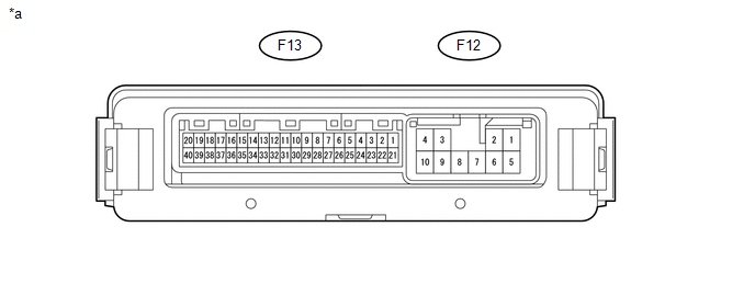
1. CHECK 4 WHEEL DRIVE CONTROL ECU
 Text in Illustration
|
*a |
Component with harness connected (4 Wheel Drive Control ECU) |
- |
- |
(a) Measure the resistance and voltage according to the value(s) in the table below.
|
Terminal No. (Symbol) |
Wiring Color |
Terminal Description |
Condition |
Specified Condition |
|---|---|---|---|---|
|
F13-12 (SLS) - F12-10 (GND) |
L - W-B |
Differential lock indicator switch |
Ignition switch ON Rear differential FREE |
10 to 14 V |
|
Ignition switch ON Rear differential LOCK |
Below 1.5 V |
|||
|
F13-15 (R) - F12-10 (GND) |
R - W-B |
Differential lock switch input |
Ignition switch ON Differential lock switch not pressed |
11 to 14 V |
|
Ignition switch ON Differential lock switch pressed and held |
Below 1.5 V |
|||
|
F13-20 (CANH) - F13-40 (CANL) |
BE - W |
HIGH-level CAN bus wire - LOW-level CAN bus wire |
Ignition switch off Cable disconnected from negative (-) battery terminal |
54 to 69 Ω |
|
F13-21 (+B) - F12-10 (GND) |
W - W-B |
ECU power supply |
Always |
10 to 14 V |
|
F12-1 (SL+) - F12-10 (GND) |
B - W-B |
Differential lock coil drive output (continuity with IG when operating) |
Ignition switch ON Rear differential free |
Below 1.5 V |
|
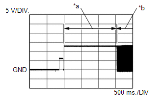
Ignition switch ON Switching between free and locked (Condition: A or C) |
Pulse generation (See waveform 1) |
|||
|
Ignition switch ON Rear differential locked (Condition B) |
Pulse generation (See waveform 1) |
|||
|
F12-4 (IG) - F12-10 (GND) |
Y - W-B |
ECU and actuator power supply |
Ignition switch ON |
11 to 14 V |
|
F12-5 (SL-) - F12-10 (GND) |
W - W-B |
Differential lock coil drive output (continuity with GND when operating) |
Ignition switch ON Rear differential free |
Below 1.5 V |
|
Ignition switch ON Rear differential switching between free and locked (Condition: A or C) |
Pulse generation (See waveform 2) |
|||
|
Ignition switch ON Rear differential locked (Condition B) |
Pulse generation (See waveform 2) |
|||
|
F12-10 (GND) - Body ground |
W-B - Body ground |
Ground |
Always |
Below 1 Ω |
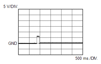
(b) Waveform 1
(1) Rear differential in locked condition
|
Item |
Content |
|---|---|
|
Tester Connection |
F12-1 (SL+) - F12-10 (GND) |
|
Tool Setting |
5 V/DIV., 500 ms./DIV. |
|
Condition: A |
Ignition switch ON Switching between free and locked |
|
Condition: B |
Ignition switch ON Rear differential locked |
|
*a |
Condition: A |
|
*b |
Condition: B |
(2) Rear differential not in locked condition (switching between free and locked)
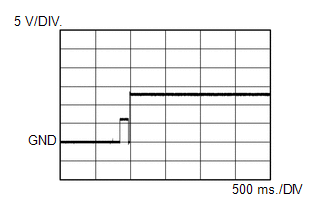
|
Item |
Content |
|---|---|
|
Tester Connection |
F12-1 (SL+) - F12-10 (GND) |
|
Tool Setting |
.5 V/DIV., 500 ms./DIV. |
|
Condition: C |
Ignition switch ON Switching between free and locked |
(c) Waveform 2
(1) Rear differential in locked condition
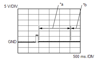
|
Item |
Content |
|---|---|
|
Tester Connection |
F12-5 (SL-) - F12-10 (GND) |
|
Tool Setting |
5 V/DIV., 500 ms./DIV. |
|
Condition: A |
Ignition switch ON Switching between free and locked |
|
Condition: B |
Ignition switch ON Rear differential locked |
|
*a |
Condition: A |
|
*b |
Condition: B |
(2) Rear differential not in locked condition (switching between free and locked)
|
Item |
Content |
|---|---|
|
Tester Connection |
F12-5 (SL-) - F12-10 (GND) |
|
Tool Setting |
5 V/DIV., 500 ms./DIV. |
|
Condition: C |
Ignition switch ON Switching between free and locked |
 Diagnosis System
DIAGNOSIS SYSTEM
1. DESCRIPTION
The 4 wheel drive control ECU records DTCs when the ECU detects a malfunction
in the ECU itself or in system circuits.
The DTCs can be read through the DLC3 of the ...
 Dtc Check / Clear
DTC CHECK / CLEAR
1. CHECK DTC
(a) Check the DTCs.
(1) Turn the ignition switch off.
(2) Connect the Techstream to the DLC3.
(3) Turn the ignition switch to ON.
(4) Turn the Techstream on.
(5) ...
Other materials:
Reassembly
REASSEMBLY
PROCEDURE
1. INSTALL GENERATOR DRIVE END FRAME BEARING
(a) Using SST and a press, press in a new generator drive end frame bearing.
SST: 09950-60010
09951-00470
SST: 09950-70010
09951-07100
(b) Fit the ta ...
Rear Door(for Double Cab)
Components
COMPONENTS
ILLUSTRATION
ILLUSTRATION
ILLUSTRATION
ILLUSTRATION
ILLUSTRATION
Adjustment
ADJUSTMENT
CAUTION / NOTICE / HINT
HINT:
Use the same procedures for both the LH and RH sides.
The procedure described below is for the LH side.
Centering bolts ...
Open in Stop Light Switch Circuit (C1425)
DESCRIPTION
The skid control ECU (brake actuator assembly) detects the brake operating conditions
through a signal transmitted by the stop light switch.
The skid control ECU incorporates a circuit to detect an open circuit. This DTC
is output when an open circuit is detected in the stop light ...
